Contact piece of plate link chain for conical disc winding contact part driving device and plate link chain

A transmission device, the technology of flat chain, applied in the field of flat chain

Inactive Publication Date: 2004-09-08
SCHAEFFLER TECH AG & CO KG
View PDF0 Cites 10 Cited by
  • Summary
  • Abstract
  • Description
  • Claims
  • Application Information

AI Technical Summary

Problems solved by technology

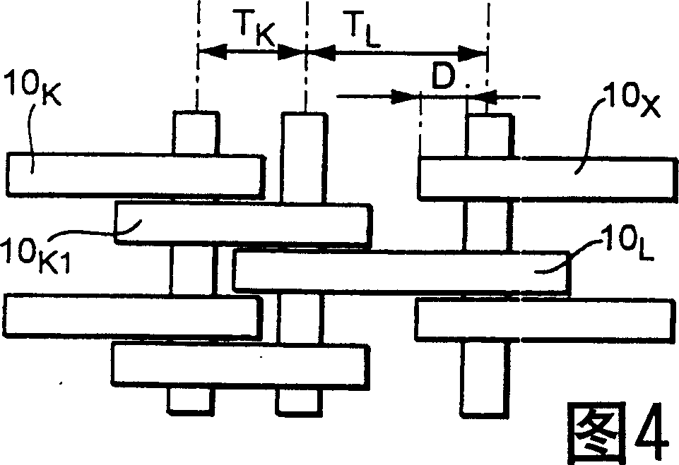
[0012] In the structure shown in FIG. 4, which is the same three-link arrangement as the chain in FIG. top tab 10 K The tab 10 after that no longer follows the tab 10 on the right in the adjacent column K the splice 10 K1 overlap, thereby making the tab 10 X May move laterally on pin or rocker pairs perpendicular to the longitudinal direction of the flat link chain

Method used


Image

  • Contact piece of plate link chain for conical disc winding contact part driving device and plate link chain
  • Contact piece of plate link chain for conical disc winding contact part driving device and plate link chain
  • Contact piece of plate link chain for conical disc winding contact part driving device and plate link chain

Examples


Embodiment Construction

[0031] Figure 6 shows a side view of the tabs used to form a flat link chain according to the invention. FIG. 5 shows a top view of a flat link chain assembled from such webs, wherein, for the sake of clarity, the top view of FIG. 5 is shown more simplified and arranged in a grid relative to the top views of FIGS. 1 , 3 and 4 .

[0032] According to FIG. 6 , a first web type is formed by a shorting web 10 , which is constructed similarly to the web shown in FIG. 2 . The vertical section thickness of this tab 10 is also D, and its longitudinal hole 18 has a predetermined length L measured along the longitudinal direction of the tab. K . In addition to the short link 10, there is also a long link 20, which differs from the short link 10 in that it has a longer length L L , and the difference is that it is formed with a protrusion 22 having a length F at one end. The lug 20 can be inserted into the flat link chain in two directions, ie with the protrusion 22 pointing to the ri...


PUM


Abstract

A plate-link chain formed from short plate links and long plate links. The long plate links have an extension at one end. The installation direction of the long plate links is such that their extensions overlap plate links in an adjacent row and that are next in order in the longitudinal direction of the plate-link chain.

Description

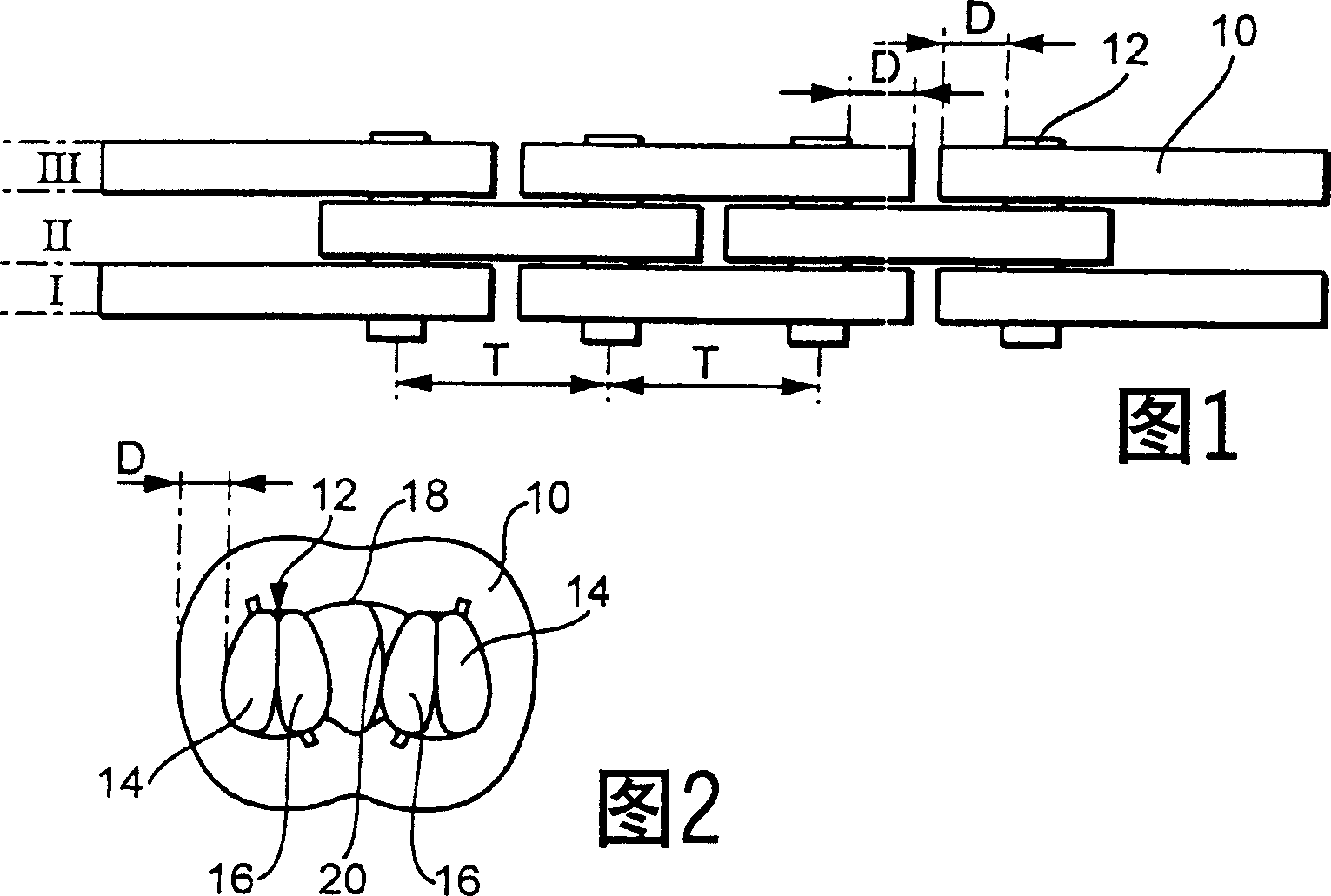
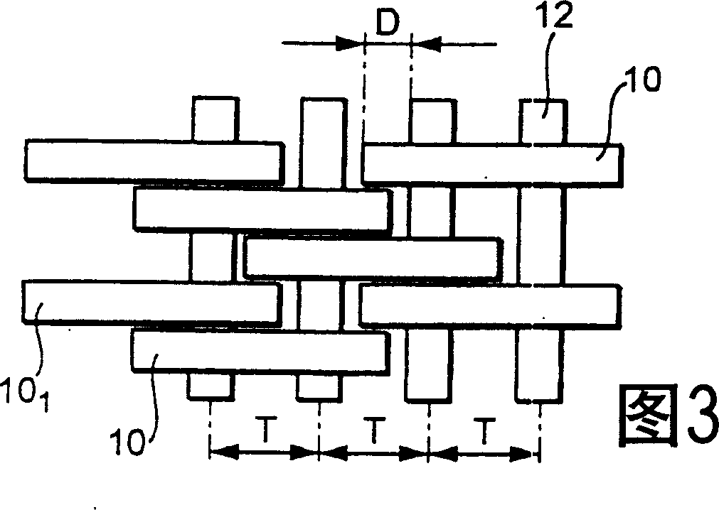
technical field [0001] This invention relates to tabs for a variety of different flat ring chains for cone-disc wrap-around contact transmissions. The invention also relates to flat link chains assembled from these tabs. Background technique [0002] FIG. 1 shows a plan view of a fragment of a known flat-link chain, for example a wrap-around contact device for a cone-disc wrap-around contact drive. This type of cone-and-disc drive has two cone-disk pairs on which a flat-ring chain is wound. In order to continuously adjust the transmission ratio of such a cone-wrapping contact transmission, the distance between the cones of these cone pairs is adjusted oppositely. [0003] This flat link chain is assembled from individual tabs 10 arranged in a plurality of side-by-side columns I, II, III etc. extending longitudinally of the flat link chain. At least some of the tabs of adjacent columns are staggered from each other so that the pins 12 traversing the flat link chain facilit...

Claims


Application Information

Patent Timeline
Patent Type & Authority Applications(China)
IPC IPC(8): F16G13/06F16G5/18
CPCF16G5/18G02F1/133621G02F1/133615G02F1/133553
Inventor 安德烈·托伊贝特安德烈·林嫩布吕特
Owner SCHAEFFLER TECH AG & CO KG
Why Eureka
Try Eureka