Pipeline evacuating valve

A technology for emptying valves and pipelines, which is applied in the direction of valve lifts, valve details, valve devices, etc., and can solve problems affecting the next water supply, pipelines that cannot be emptied, and pressure differences in pipelines, and achieve good emptying effects and simple and reasonable structures , The effect of pipe material saving

Inactive Publication Date: 2004-09-08
陈新贤
View PDF0 Cites 1 Cited by
  • Summary
  • Abstract
  • Description
  • Claims
  • Application Information

AI Technical Summary

Problems solved by technology

[0002] At present, the existing pipeline emptying valve is composed of a valve body with an inlet and an outlet, a spring-controlled float, a rubber plug, and an air intake pipe. The rubber plug blocks the air intake pipe to prevent water ingress. When negative pressure is generated in the pipeline, the air inlet hole is opened to complete the pipeline emptying. The disadvantage is that after the pipeline is emptied, there is a pressure difference between the inside and the outside of the pipeline, which will affect the next water supply; when the height of the emptying pipeline is less than 3 meters, the inside of the pipeline will The negative pressure generated cannot overcome the pressure of the spring, the intake pipe cannot be opened, and the pipe cannot be emptied; the height of the exhaust pipe is greater than 5 meters.

Method used


Image

  • Pipeline evacuating valve
  • Pipeline evacuating valve

Examples


Embodiment Construction

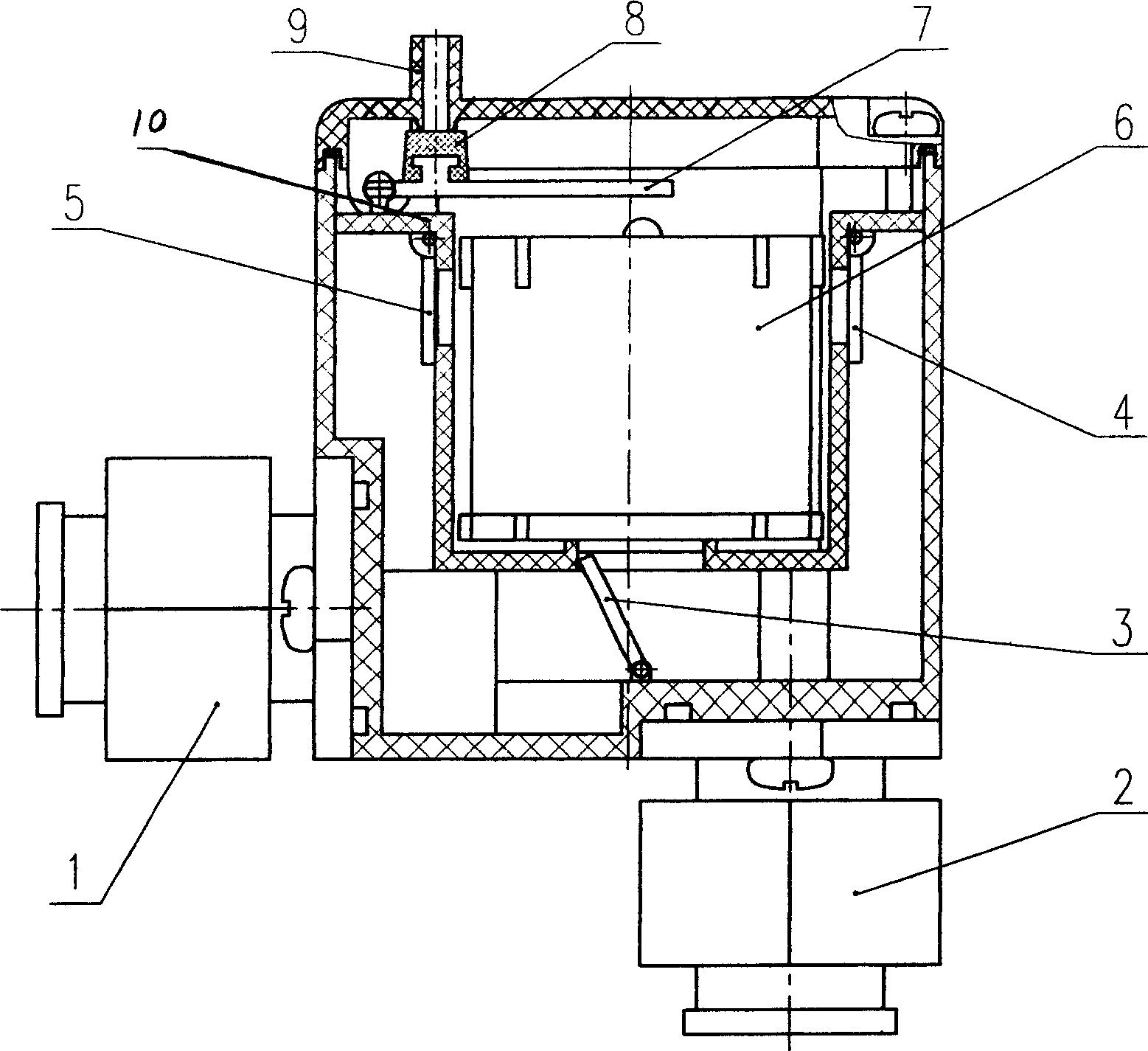
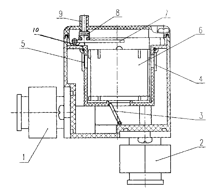
[0007] The pipeline emptying valve shown in the figure is a valve body 10 with a water inlet 1 and a water outlet 2. The valve body 10 is provided with a two-way door 3 and a float 6, and the left side valve wall of the two-way door 3 is opened with a left single To the door 5, an intake pipe 9 is opened on the top valve wall. The upper part of the inner side of the valve body 10 is also provided with a lever 7. The top of the float 6 is aligned with the movable end of the lever 7, and the fixed end of the lever 7 is hinged on the wall of the valve body 10 and installed on the The sealing lining 8 on the lever 7 covers the port of the exhaust pipe 9 when the lever 7 is pushed up, and opens the port of the exhaust pipe 9 when the lever 7 is lowered. In the valve body 10, a right one-way door 4 is added to the right side valve wall of the two-way door 3. When supplying water, water enters from the water inlet 1, the left one-way door 5 is closed, the two-way door 3 is driven from th...


PUM


Abstract

The present invention discloses one kind of pipeline evacuating valve. The pipeline evacuating valve includes valve body with water inlet and water outlet, bi-directional door with single-directional door on the left wall and inlet pipe on the top wall and float inside the valve body, lever in the upper part with movable end aligning the top of the float and fixed end hinged to the valve wall, sealing sheet on the lever capable of covering the gas exhaust port when the lever is pushed upwards and opening the gas exhaust port when the lever is made to fall down. The present invention can realize reverse water supply and automatic evacuating pipeline after stopping water supply, and is suitable for water supply and gas supply pipeline.

Description

Technical field [0001] The invention belongs to a pipeline on-off control device. Background technique [0002] At present, the existing pipeline emptying valve is composed of a valve body with inlet and outlet ports, spring control floats, rubber plugs, air inlet pipes, etc. The rubber plugs block the air inlet pipe to prevent water from entering, and water flows out of the air inlet pipe to stop the water supply. When the negative pressure is generated in the pipeline, the air inlet is opened to complete the pipeline emptying. The disadvantage is that after the pipeline is empty, there is a pressure difference between the pipeline and the outside, which affects the next water supply; when the emptying pipeline is less than 3 meters in height, the inside of the pipeline The negative pressure generated cannot overcome the pressure of the spring, the intake pipe cannot be opened, and the pipe cannot be emptied; the height of the exhaust pipe is greater tha...

Claims


Application Information

Patent Timeline
IPC IPC(8): F16K1/00F16K31/20
Inventor 陈新贤
Owner 陈新贤
Why Eureka
Try Eureka