
Eureka
For R&D, Eureka makes reading and utilizing patents & technical documents easy.
Eureka AIR
Designed for self-driven R&D workflows. Generate viable solutions, solve complex R&D challenges, empower your innovation with AI.

Eureka Materials
Designed for material experts only. Revolutionize your material R&D, from search, analyze, to developing new materials.

TechResearch
Generate reliable direction feasibility study reports for your R&D in just a few steps.

TechSeek
Discover and master advanced knowledge NOW. Basics, ideas, possibilities, all at once.

TechMind
As an expert in R&D Theories, TechMind can generates customized viable solutions instantly.

TechRisk
Analyze your overall solution with one click, know your potential R&D risks in advance.

TechMonitor
Get weekly tech updates, stay abreast of the latest tech innovations and key insights.
Pressurized container
A technology of internal pressure container and pressure surface, which is applied to the pressure surface and pressure surface of the intake and exhaust cylinders, and can solve problems such as increasing tensile stress
- Summary
- Abstract
- Description
- Claims
- Application Information
AI Technical Summary
Problems solved by technology
Method used
Image

Examples
Embodiment 1
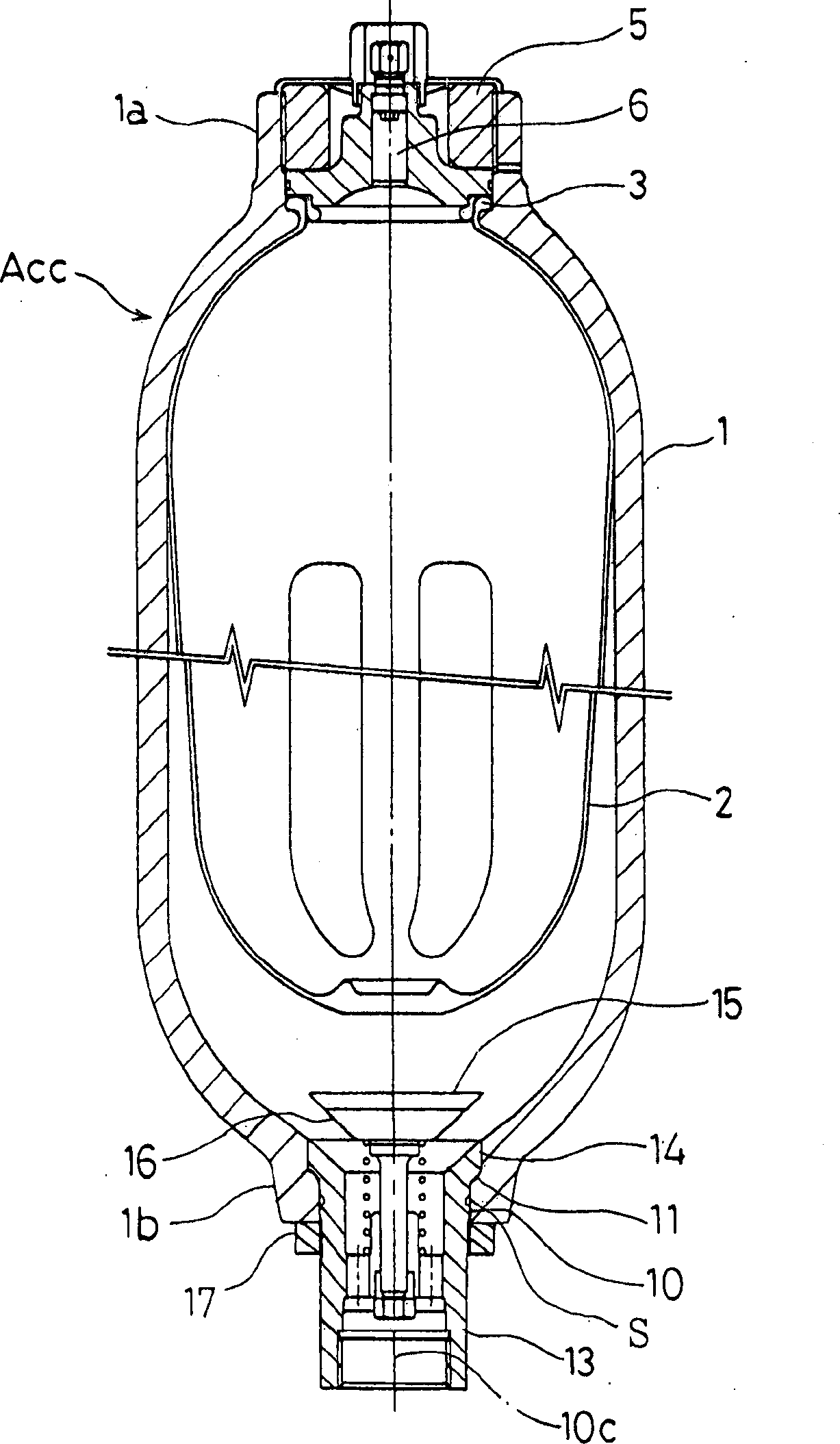
[0021] refer to figure 1 ~ Fig. 3 introduces the embodiment of the present invention.
[0022] The accumulator ACC has an air bag 2 built in the container main body 1 . The airbag 2 is a pleated airbag, which is folded into a predetermined shape by forming creases.
[0023] The flange 3 of the airbag 2 is fastened to the upper part 1 a of the container body 1 and fixed by the lid body 5 . An intake and exhaust port 6 communicating with the inside of the airbag 2 is provided on the cover body 5 .
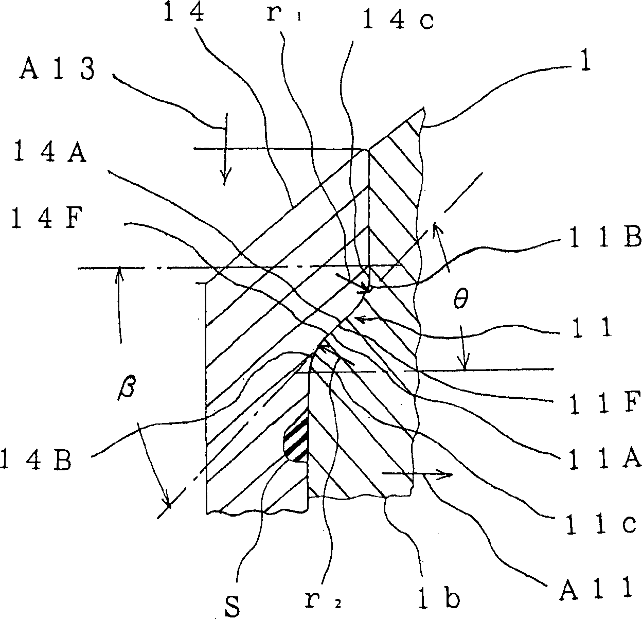
[0024] A through hole 10 is provided at the bottom 1 b of the container main body 1 , and the intake and exhaust cylinder 13 is inserted into the through hole 10 through an O-ring S. As shown in FIG. The flange portion 14 of the intake / exhaust cylinder 13 is press-welded to the receiving portion 11 of the through hole 10 .
[0025] The pressure-receiving tapered surface 11A of the pressure-receiving surface 11F of the receiving portion 11 is outwardly upward, that is, inclined in...
experiment example
[0041] Regarding the accumulator of this embodiment, when the tensile load is calculated using the finite element method, and the total load acting on the flange portion 14 is 332,620N, the inner side of the pressure surface 14F of the flange portion 14 is pressurized and adjusted The maximum tensile stress of R surface 14B is 106N / mm 2 , In addition, the maximum tensile load of the outer pressure-receiving surface 11B of the pressure-receiving surface 11F of the receiving part 11 is 212N / mm 2 .
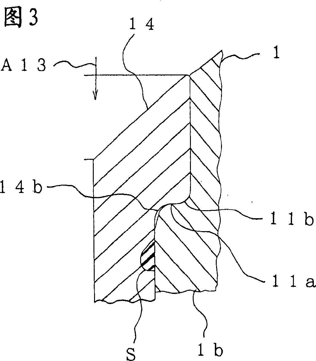
[0042] On the other hand, in the conventional example in which both ends of the R plane and the horizontal plane are connected as shown in FIG. The maximum tensile stress of the inner side pressure surface R surface 14b is 259N / mm 2 , the maximum tensile stress of the outer compression R surface 11b of the receiving part is 288N / mm 2 .
[0043] The above shows that, compared with the conventional example, the maximum tensile stress generated on the pressure-receiving surface and ...
no. 2 example
[0045] refer to Figure 4 ~ Figure 7 The second embodiment of the present invention will be described.
[0046] This embodiment is an embodiment in which the maximum tensile stress of each surface is calculated by changing the radii r1 and r2 of the outer pressure-adjusting R surface 11B and the inner pressure-adjusting R surface 14B, using the method shown in the first embodiment. .
[0047] Such as Figure 4 The radii r1 and r2 of the adjustment R surfaces 11B and 14B shown are 0.4 mm, and the maximum tensile stress of the pressure adjustment R surface 11B on the outside of the container body 1 is 246 N / mm at this time 2, In addition, the maximum tensile stress of the inner pressurization adjustment R surface 14B of the intake and exhaust cylinder 13 is 322N / mm 2 .
[0048] Such as Figure 5 The radii r1 and r2 of the adjustment R surfaces 11B and 14B shown are 1.0mm, and at this time the maximum tensile stress of the pressure adjustment R surface 11B on the outside of ...
PUM
 Abstract
Description
Claims
Application Information
 - R&D Engineer
- R&D Manager
- IP Professional
- Industry Leading Data Capabilities
- Powerful AI technology
- Patent DNA Extraction
Browse by: Latest US Patents, China's latest patents, Technical Efficacy Thesaurus, Application Domain, Technology Topic, Popular Technical Reports.
© 2024 PatSnap. All rights reserved.Legal|Privacy policy|Modern Slavery Act Transparency Statement|Sitemap|About US| Contact US: help@patsnap.com