Super grinding machine, super grinding method rolling piece and rolling bearing

A super grinding, workpiece technology, applied in rolling contact bearings, roller bearings, shafts and bearings, etc., can solve problems such as difficult to produce extended life

Inactive Publication Date: 2004-10-13
NSK LTD
View PDF1 Cites 16 Cited by
  • Summary
  • Abstract
  • Description
  • Claims
  • Application Information

AI Technical Summary

Problems solved by technology

[0006] The various methods of the aforementioned related art can make a rolling element having a rolling surface whose generatrix is ​​a straight shape or a shape consisting only of arc segments, but c

Method used


Image

  • Super grinding machine, super grinding method rolling piece and rolling bearing
  • Super grinding machine, super grinding method rolling piece and rolling bearing
  • Super grinding machine, super grinding method rolling piece and rolling bearing

Examples


example 1

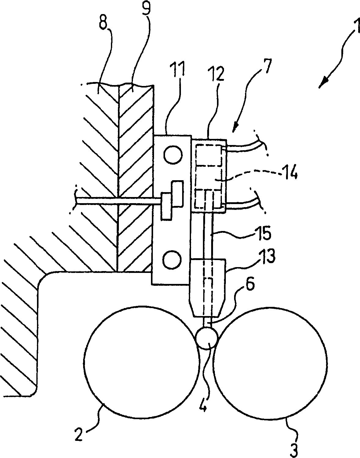
[0072] A kind of machining process of the rolling surface of the rolling member 4 will be described below so that it has the same Figure 11 The ideal logarithmic shape shown therein acts as a convex surface (recess) such that the radius of curvature varies smoothly.

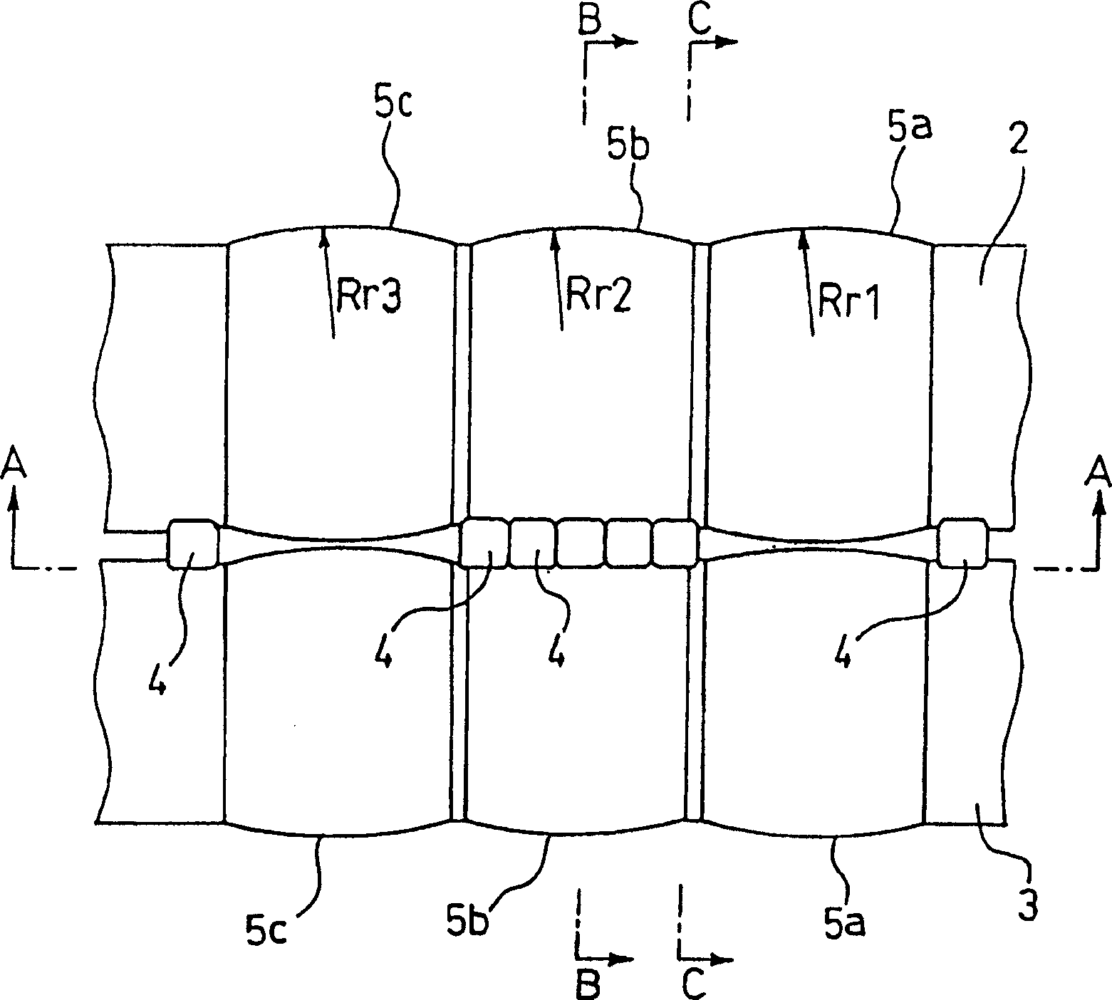
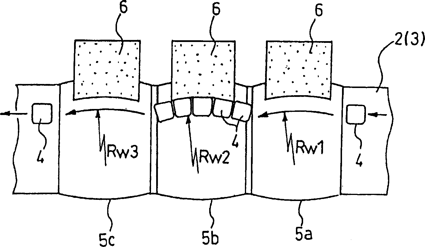
[0073] Approximating the ideal logarithmic shape with arc segments gives three arc segments with radii of curvature (Rwl, Rw2, Rw3) of 300mm, 1500mm and 4500mm respectively. The radius of curvature of the driving rolling 2, 3 raised parts 5a, 5b, 5c is determined according to the central angle of the workpiece, the diameter of the driving roller 2, 3 and the diameter of the rolling element 4, so that each movement track of the rolling element 4 has 300mm, 1500mm and 4500mm respectively The radii of curvature Rw1, Rw2 and Rw3, as a result, Rr1, Rr2 and Rr3 were determined to be 970mm, 4400mm and 13000mm, respectively.

[0074] Adopt the driving roller 2,3 that has the convex portion 5a, 5b, 5c of the curvature rad...

example 2

[0077] Although Example 1 is described with reference to the case in which supergrinding is performed using drive rollers each having a raised portion corresponding to each approximate arc segment provided at a corresponding one position, at each approximate arc segment The amount of removal required at a site can actually vary. Therefore, the removal amount at the large radius of curvature needs to be increased. Secondly, since supergrinding at small radii of curvature is prone to instability, it is often advisable to use drive rollers with large radii of curvature for the last and first raised portions.

[0078] Therefore, the rolling elements are superground by a supergrinding machine, which consists of driving rollers 2, 3, which have six raised portions with radii of curvature Rr1, Rr2 of 13000 mm, 13000 mm, 970 mm, 4400 mm, 4400 mm and 13000 mm, respectively , Rr3, Rr4, Rr5, Rr6, as Figure 12 shown in.

[0079] It thus becomes apparent that a rolling element having a...

example 3

[0081] A process of machining the rolling surface of the rolling member 4 will be described below so that it is as Figure 14 Shown in has an ideal logarithmic shape as a convex surface.

[0082] Approximating the ideal logarithmic shape with arc segments gives three arc segments with respective radii of curvature (Rwl, Rw2, Rw3) of 9000mm, 3400mm and 600mm. Therefore, three convex portions are provided so that the respective motion tracks of the rolling member 4 have curvature radii Rw1, Rw2 and Rw3 of 9000mm, 3400mm and 600mm respectively, as Figure 15 shown in. Next, a convex portion is provided with a trajectory having a curvature radius Rw4 of 9000mm, so that the rolling member can finally be superground at a large curvature radius to stabilize the supergrinding.

[0083] The radius of curvature of each raised portion of the driving rollers 2, 3 is determined according to the geometric relationship between the central angle of the workpiece and the diameters of the dri...


PUM


Abstract

Driving rollers 2, 3 which rotate in the same direction are arranged in parallel to each other. A plurality of convex portions 5a, 5b, 5c having different radii of curvature Rr1, Rr2 and Rr3 are formed along the axial direction at opposing positions on the driving rollers 2, 3. A rolling element 4 which is fed into the gap between the driving rollers 2, 3 and rotated is moved along tracks having different radii of curvature Rw1, Rw2 and Rw3 in the axial direction. There is provided a superfinishing grindstone 6 which is pressed on the rolling surface of the rolling element 4 moving on tracks having different radii of curvature to superfinish the rolling surface of the rolling element 4.

Description

technical field [0001] The present invention relates to a supergrinding machine and method for supergrinding the periphery of cylindrical workpieces such as to be used as cylindrical rollers for rolling bearings, supergrinding rolling elements and rolling bearings comprising such rolling elements. Background technique [0002] Generally speaking, the rolling elements to be used as cylindrical rollers for rolling bearings are ground. The roller thus ground is then subjected to supergrinding on its rolling surface, ie on its periphery. [0003] As a mechanism for realizing super-grinding, there has heretofore been adopted a pair of drive rollers that rotate in the same direction with a rolling member placed therebetween so that the rolling member is driven by a super-grinding stone with a It is rotated while being pressed against the rolling surface of the rolling member with a predetermined pressure to super grind the rolling surface of the rolling member (see, eg, Reference...

Claims


Application Information

Patent Timeline
IPC IPC(8): B24B5/18B24B5/37B24B33/04B24B35/00F16C33/34
CPCF16C33/34B24B5/37B24B33/04F16C23/08B24B35/00B24B5/18
Inventor 鎌村有宏井手义郎苅田智治中原伊织村井隆司藤井修水野浩树
Owner NSK LTD
Why Eureka
Try Eureka