Surface light source device

A surface light source and light source technology, which is applied in the direction of optics, nonlinear optics, diffuser elements, etc., can solve the problems of uneven light output and inability to change the local luminance of light, and achieve uniform output of light, change of luminance of light output, and uniform light output Effect

Inactive Publication Date: 2004-10-13
HONG FU JIN PRECISION IND (SHENZHEN) CO LTD +1
View PDF3 Cites 0 Cited by
  • Summary
  • Abstract
  • Description
  • Claims
  • Application Information

AI Technical Summary

Problems solved by technology

[0006] In order to overcome the shortcomings of the surface light source device in the prior art that the light output is uneven and the local luminance cannot be changed, the present invention provides a surface light source device that emits uniform light and can change the local luminance

Method used


Image

  • Surface light source device
  • Surface light source device
  • Surface light source device

Examples


Embodiment Construction

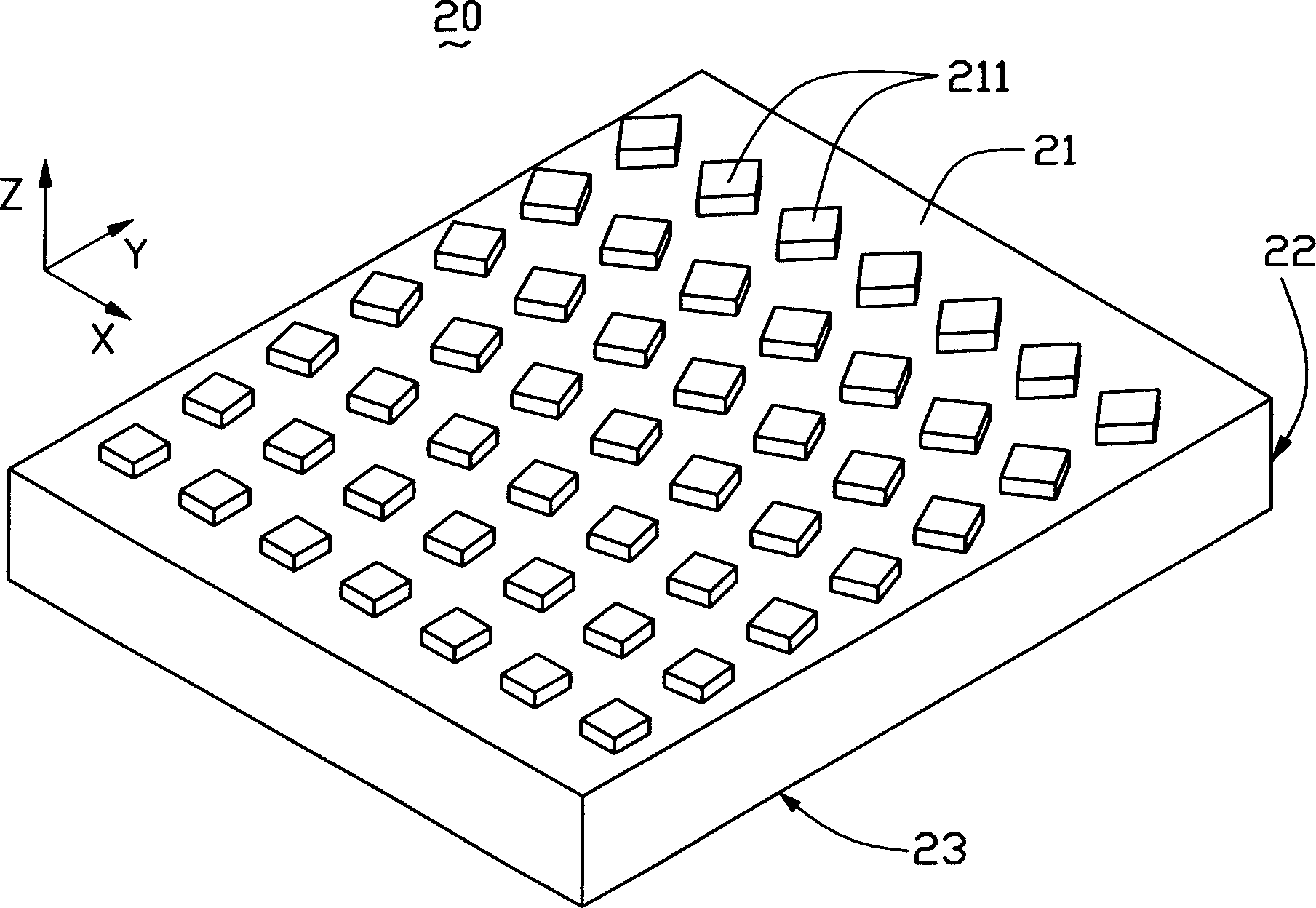
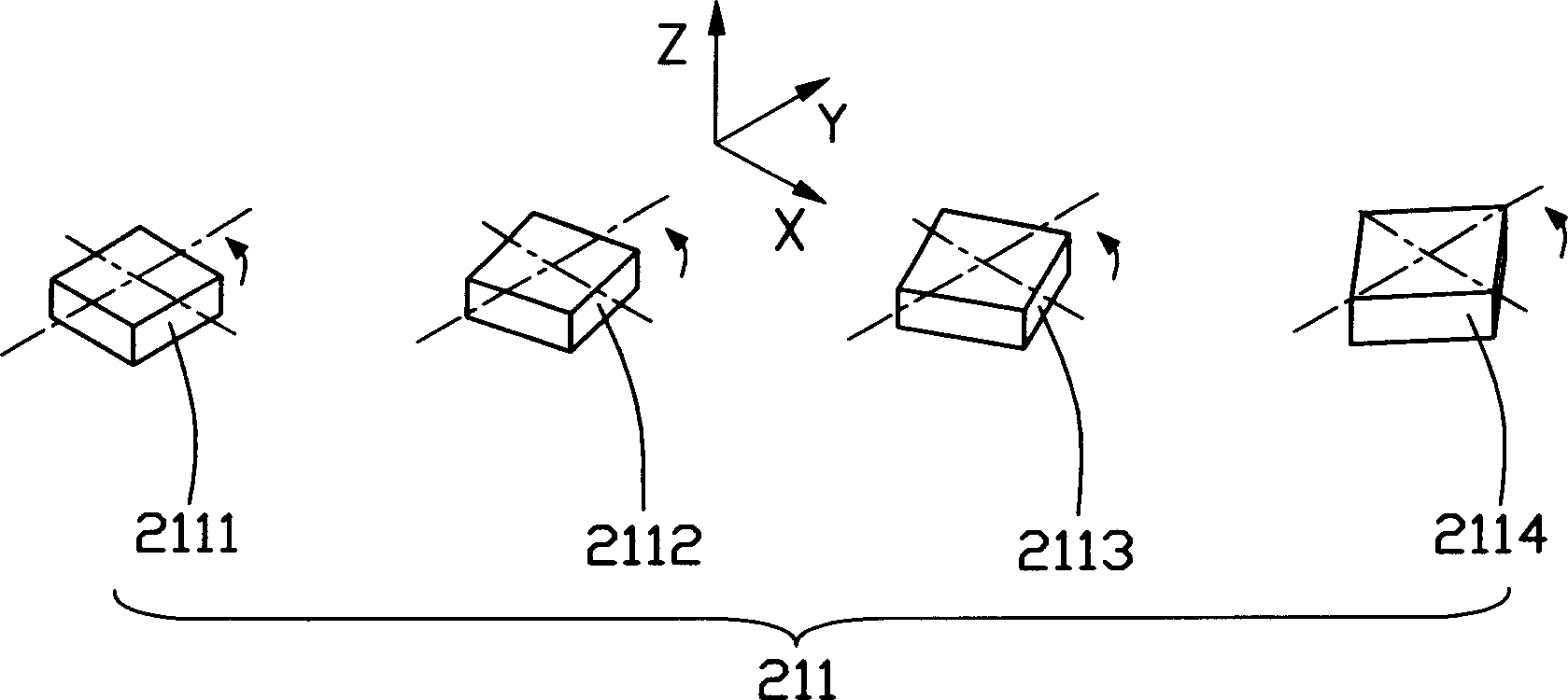
[0016] Light guide plate of the present invention such as figure 2 shown. The light guide plate 20 includes a light incident surface 22 for receiving incident light, a light exit surface 23 adjacent to the light incident surface 22, and a bottom surface 21 opposite to the light exit surface 23, wherein the bottom surface 21 is provided with Scattering point array 211, the arrangement of scattering points in the scattering point array 221 is as follows image 3 shown. Each scattering point in the scattering point array 221 is a rectangular scattering point with the same shape and size, and they are distributed on the bottom surface 21 with the same density. Each scattering point in the scattering point array 211 has a different angular distribution relative to the horizontal plane XY, that is, the scattering points 2112, 2113, 2114 rotate at different angles along the Z axis relative to the scattering point 2111, wherein the Z axis and the light incident surface 22 parallel...


PUM


Abstract

The invention relates to a plane light source device, including at least a light guide board with at least an incident light surface, and at least a corresponding light source opposite to on one side of the incident light surface, and the light guide board includes a light-emitting surface next the incident light surface, and a bottom opposite to the light-emitting surface, where the bottom surface is set with scattering point array, which includes many scattering points with the same shape which are distributed at different angles with the incident light surface.

Description

【Technical field】 [0001] The invention relates to a surface light source device. 【Background technique】 [0002] Liquid crystal displays are mainly used in various information, communication, and consumer products, such as personal computers, LCD TVs, mobile phones, video phones, and PDAs. Because the liquid crystal display panel itself does not have luminous properties, in order to obtain a good visual effect, a surface light source device is required to provide it with uniform and high-intensity plane light. [0003] At present, surface light source devices in the prior art such as figure 1 As shown, the surface light source device 10 includes a light guide plate 1, a reflection plate 2 located on the bottom surface of the light guide plate 1 (not marked), a diffuser plate 3 located on the light exit surface (not marked) of the light guide plate 1, and a diffuser plate 3 located on the light incident surface of the light guide plate 1. (not marked) the light source 6 and...

Claims


Application Information

Patent Timeline
Patent Type & Authority Applications(China)
IPC IPC(8): G02B5/02G02F1/13357
Inventor 林志泉
Owner HONG FU JIN PRECISION IND (SHENZHEN) CO LTD
Why Eureka
Try Eureka