
LED signal lamp and constant-current driving circuit thereof

A technology of constant current drive and LED lamp group, which is applied in the direction of electric lamp circuit layout, electric light source, lighting device, etc., and can solve the problem of fixed luminous brightness, design of power supply characteristics of mine locomotives with constant current drive circuit, and long-distance signal lamps cannot be clearly seen. identification and other issues

Inactive Publication Date: 2015-07-08
SHENZHEN OCEANS KING LIGHTING ENG CO LTD +1
View PDF3 Cites 0 Cited by
  • Summary
  • Abstract
  • Description
  • Claims
  • Application Information

AI Technical Summary

Problems solved by technology

[0003] However, the traditional constant current drive circuit is not specially designed for the power supply characteristics of mining locomotives. The brightness of LEDs is almost fixed, and long-distance signal lights may not be clearly identifiable.

Method used


Image

  • LED signal lamp and constant-current driving circuit thereof
  • LED signal lamp and constant-current driving circuit thereof

Examples


Embodiment Construction

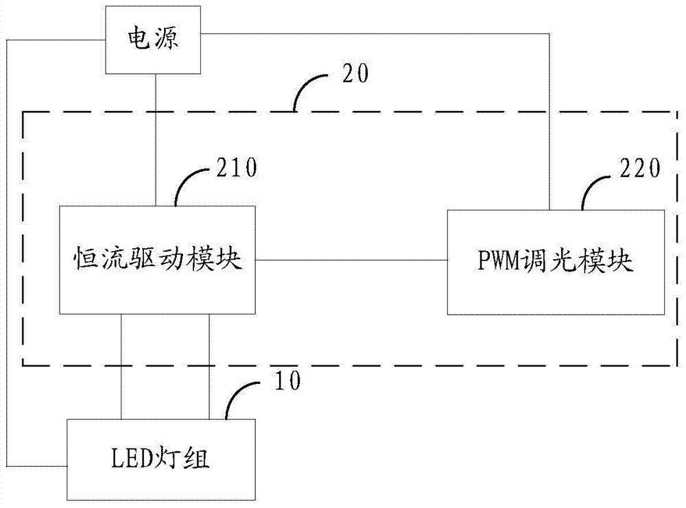
[0018] Such as figure 1 Shown is the constant current drive circuit module diagram of the LED signal lamp.

[0019] The constant current driving circuit 20 of the LED signal lamp is connected to the LED lamp group 10, and includes a constant current driving module 210 with more than two constant current output terminals and a PWM dimming module 220 connected with the constant current driving module 210 to realize stepless dimming.

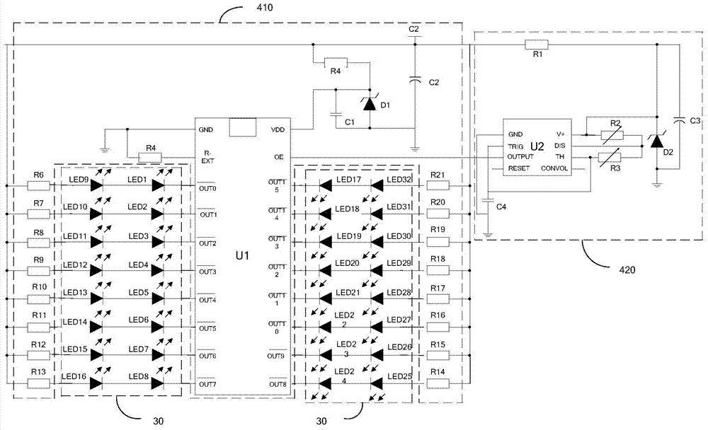
[0020] Such as figure 2 Shown is a schematic diagram of a constant current drive circuit for an LED signal lamp in an embodiment.

[0021] The constant current drive circuit 40 of the LED signal light includes a constant current drive module 410 with 16 constant current output terminals and a PWM dimming module 420 connected with the constant current drive module 410 to realize stepless dimming.

[0022] Wherein, the constant current driving module 410 determines the constant current chip U1 that outputs current according to the PWM signal, and ...


PUM


Abstract

A constant-current driving circuit for LED signal lamps is connected with an LED lamp group, and comprises a constant-current driving module provided with more than two constant-current output ends. The constant-current driving circuit further comprises a dimming module which is connected with the constant-current driving module to realize stepless dimming. An LED signal lamp is further disclosed. The constant-current driving circuit of the invention has a dimming function and can meet the needs of different distances.

Description

technical field [0001] The invention relates to the field of electronic lighting, in particular to an LED signal lamp and a constant current driving circuit thereof. Background technique [0002] Signal lights are an important tool to strengthen road traffic management, reduce traffic accidents, improve road use efficiency, and improve traffic conditions. For mining locomotives, it is often necessary to work in the roadway at night, and the requirements for signal lights are relatively high. As the main component of the signal lamp, LED needs a special driving circuit to provide constant current for it to work. [0003] However, the traditional constant current drive circuit is not specially designed for the power supply characteristics of mining locomotives. The brightness of LEDs is almost fixed, and long-distance signal lights may not be clearly identifiable. Contents of the invention [0004] Based on this, it is necessary to provide a constant current drive circuit ...

Claims


Application Information

Patent Timeline
Patent Type & Authority Applications(China)
IPC IPC(8): H05B37/02
Inventor 周明杰刘百顺
Owner SHENZHEN OCEANS KING LIGHTING ENG CO LTD
Learn More