Structured packing with increased capacity

A structured packing and quality technology, applied in lighting and heating equipment, liquefaction, water shower coolers, etc., can solve problems such as performance deterioration

Inactive Publication Date: 2004-10-20
AIR PROD & CHEM INC
View PDF7 Cites 10 Cited by
  • Summary
  • Abstract
  • Description
  • Claims
  • Application Information

AI Technical Summary

Problems solved by technology

This can lead to poor performance in terms of both mass transfer and pressure drop, especially at high flow rates

Method used


Image

  • Structured packing with increased capacity
  • Structured packing with increased capacity
  • Structured packing with increased capacity

Examples


Embodiment Construction

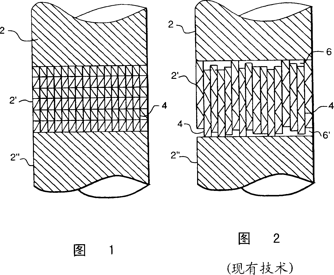
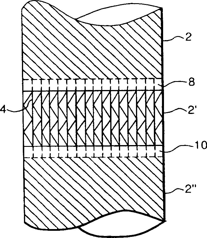
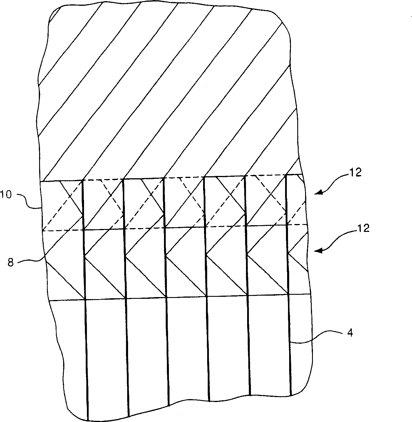
[0046] Applicants have discovered that by making a plurality of adjacent, mutually engaging layers of structured packing, it is possible to delay the onset of the mass transfer flooding phenomenon and reduce the pressure drop across the structured packing, thereby increasing the capacity of the structured packing. This is due to improved liquid drainage between layers and reduced carryover of small liquid droplets into the packing channels.

[0047] Figures 1 and 2 represent a plurality of structured packing layers (2, 2', 2 ") that can be arranged in layers in an exchange column (not shown). When separate structured packing sheets 4 are assembled into packing layers, these plates are usually due to A slight misalignment in the vertical direction due to a defect in the manufacturing process. This is shown in schematic 2, where the misalignment is exaggerated for illustrative purposes. This misalignment results in gaps (6, 6'), which are in an uncontrolled and random fashion Oc...


PUM


Abstract

At least one edge (8; 10) of a structured packing element (4) is adapted to, or includes a means for, intermeshing with an adjacent edge (10; 8) of an adjacent structured packing element. Preferably, the at least one edge is a pair of opposite edges (8, 10) that intermesh with the respective opposed edge (10, 8) of an adjacent identical element (4) so as to permit the assembly of vertically stacked layers (2, 2', 2") of intermeshing packing.

Description

technical field [0001] This invention relates to structured packing and methods for installing such packing in exchange columns to provide increased capacity. The structured packing has specialized application in cryogenic air separation processes, but it can also be used in a variety of other heat and / or mass transfer processes in which structured packing can be used. Background technique [0002] The term "column" (or "exchange column") as used herein means a distillation or fractionation column or zone, i.e., a column or a series of vertically spaced A column or zone in which the liquid and vapor phases are contacted in counterflow to effect separation of the fluid mixture by contacting the trays or plates. [0003] The term "column section" (or "section") means the area within the column that fills the column diameter. The top or bottom of a particular section or zone terminates in a liquid and vapor distributor respectively. [0004] The term "packing" means solid or...

Claims


Application Information

Patent Timeline
Patent Type & Authority Applications(China)
IPC IPC(8): B01J19/32F25J3/04F28F25/08
CPCB01J2219/33Y10S261/72F25J3/04909B01J19/32B01J2219/32258B01J2219/32213B01J2219/32272F25J3/04763B01J2219/3221F28F25/087B01J2219/32244B01J2219/32275
Inventor G·A·梅斯基S·森德
Owner AIR PROD & CHEM INC
Why Eureka
Try Eureka