Mounting structure of rubber buffer for connector of stock

A technology for rolling stock, mounting structures, used in buffers, rail car body components, transportation and packaging

Inactive Publication Date: 2004-10-20
KAWASAKI HEAVY IND LTD
View PDF1 Cites 10 Cited by
  • Summary
  • Abstract
  • Description
  • Claims
  • Application Information

AI Technical Summary

Problems solved by technology

However, in the case where the cross-section is triangular, since the number of sides of the pipe materia

Method used


Image

  • Mounting structure of rubber buffer for connector of stock
  • Mounting structure of rubber buffer for connector of stock
  • Mounting structure of rubber buffer for connector of stock

Examples


Embodiment Construction

[0037] Embodiments of the present invention will be described below with reference to the drawings.

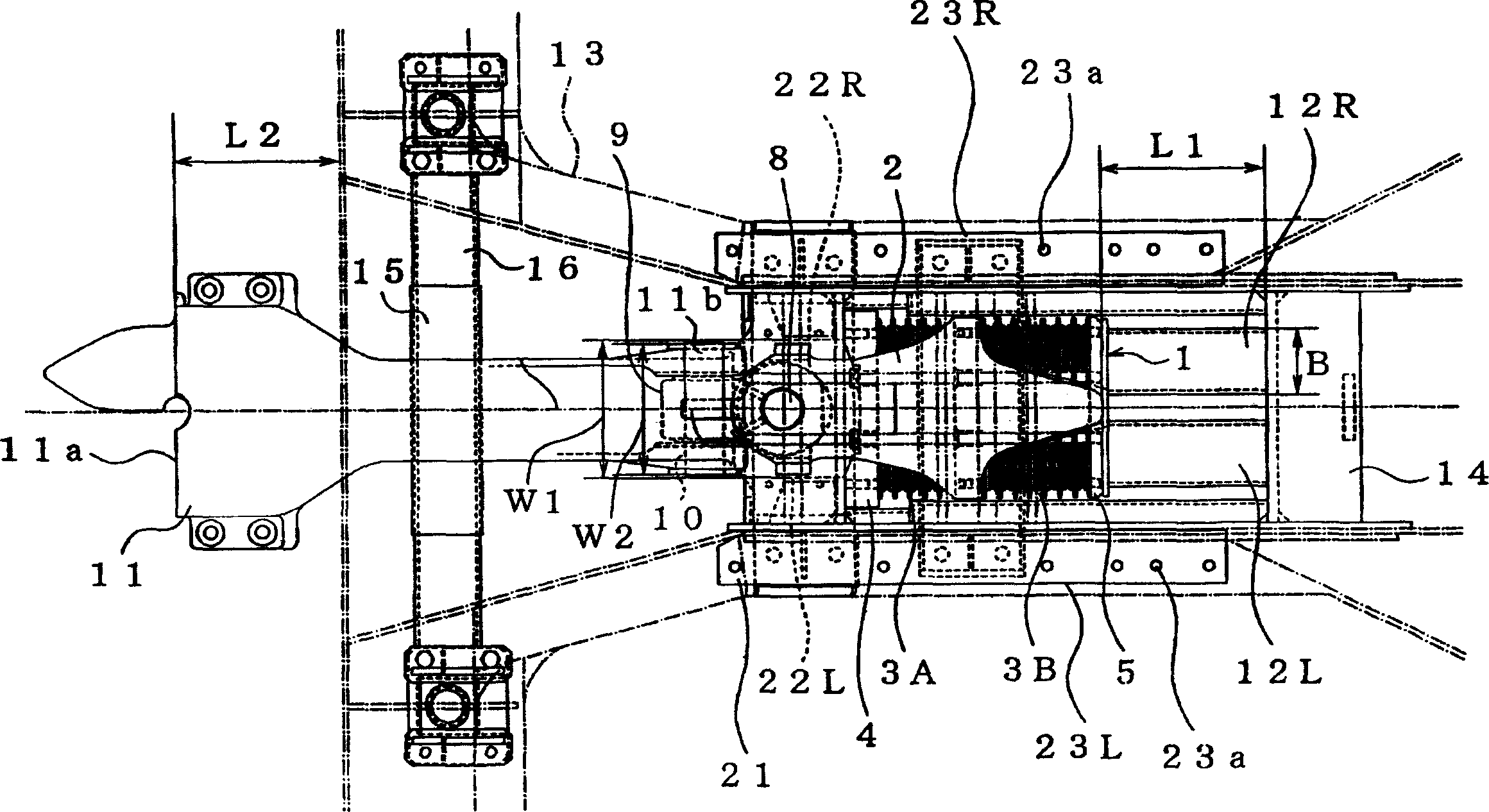
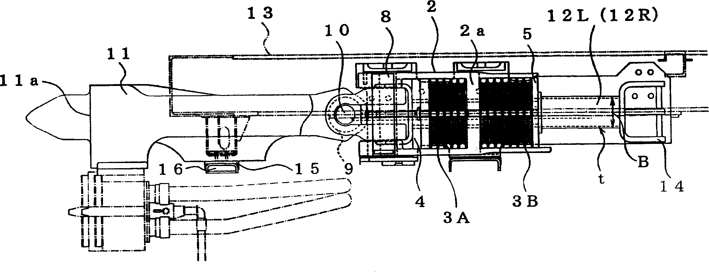
[0038] like figure 1 and figure 2 As shown, at the frontmost part (or rear end) of the railway vehicle, the rubber buffer 1 is connected to the rear end of the connector 11, and a square cylinder is arranged side by side symmetrically on the rear side of the rubber buffer 1 for absorbing Shock fittings 12L, 12R. That is, the connector 11, the rubber bumper 1, and the pipes 12L, 12R for absorbing shock are sequentially arranged in the front-rear direction of the vehicle body. The vehicle body underframe 13 bears the impact load in the front-rear direction of the vehicle body through the pipes 12L and 12R for absorbing impact. The structure of the rubber buffer 1 is basically the same as the rubber buffer described in the prior art column.

[0039] The impact-absorbing pipe members 12L, 12R are constructed in a closed-section structure (square-section pipe) having four pan...


PUM


Abstract

An installation structure for the rubber buffer of connector of rolling stock is disclosed, which can stably lead the wrinkle deformation and buffer the impact load and acceleration. The connector, rubber buffer and square tube shaped impact absorbing unit are sequentially installed to front end and back end of a rolling stock. A relational expression between the width and thickness of said impact absorbing unit is also disclosed.

Description

technical field [0001] The present invention relates to a mounting structure of a rubber buffer for a rail vehicle connector. Background technique [0002] Generally, in railroad vehicles, rubber bumpers are provided on the rear side of connectors that connect the vehicles to each other to absorb the shock generated at the time of collision. Such bumpers are slidably supported within draft lugs which are riveted to the vehicle underframe. [0003] This rubber buffer 1 such as Figure 9 As shown, it has: a frame 2 with a partition wall 2a; buffer rubbers 3A, 3B (rubber plates and metal plates overlap each other) installed respectively on the front and back of the partition wall 2a of the frame 2; Part 4 (follower plate) and supporting part 5 (rubber pad); and a pair of connection locking parts 6 that integrate the frame 2, buffer rubbers 3A, 3B, and supporting parts 4 and 5. The frame joint 9 is rotatably connected to the front end of the frame 2 via a longitudinal pin 8 ex...

Claims


Application Information

Patent Timeline
IPC IPC(8): B61G11/08B61G11/16
Inventor 田口真古川诚冈田真一山口秀行
Owner KAWASAKI HEAVY IND LTD
Why Eureka
Try Eureka