Cloth feeding mechanism of sewing machine

A cloth feeding device and sewing machine technology, applied in the direction of sewing machine components, cloth feeding mechanism, sewing equipment, etc., can solve the problems of disordered cloth feeding, damage to sewing quality, connection and removal troubles, etc., to achieve accurate cloth feeding, The effect of reducing the distance and reducing the sound

Active Publication Date: 2004-11-03
JUKI CORP
View PDF6 Cites 9 Cited by
  • Summary
  • Abstract
  • Description
  • Claims
  • Application Information

AI Technical Summary

Problems solved by technology

However, when a solenoid is used, only two types of adjustment of the feed amount can be performed when the solenoid is stretched and contracted, so there is a problem that it becomes a sewing machine without versatility.
[0033] In addition, when the above-mentioned actuator is installed outside the oil pan or under the sewing machine table, when the sewing machine is laid down, since the cloth feed adjustment body and the sewing machine move together, it is necessary to release the cloth feed adjustment body and the actuator. The connection between the two, the connection and release of the two became a troublesome work
[0034] In addition, when the actuator is installed outside the sewing machine head, outside the oil pan, or under the sewing machine table, etc., since the actuator and the cloth feed adjustment mechanism are exposed, noise will be generated when driving (especially when driving at high speed).
[0035] Especially for sewing purposes, sometimes the amount of cloth feed is changed multiple times in one sewing process. At this time, the number of times the actuator is repeatedly stopped and driven (including reverse rotation) is increased, and intermittent noise continues during sewing, which is noticeable. worsen the environment of the sewing workshop
[0036] In addition, in the structure in which the actuator and the feed adjusting body are driven by gears or timing belts, the amount of cloth feeding may be disturbed due to backlash of the gears or slack in the timing belt, etc. Problems that impair sewing quality

Method used


Image

  • Cloth feeding mechanism of sewing machine
  • Cloth feeding mechanism of sewing machine
  • Cloth feeding mechanism of sewing machine

Examples


Embodiment Construction

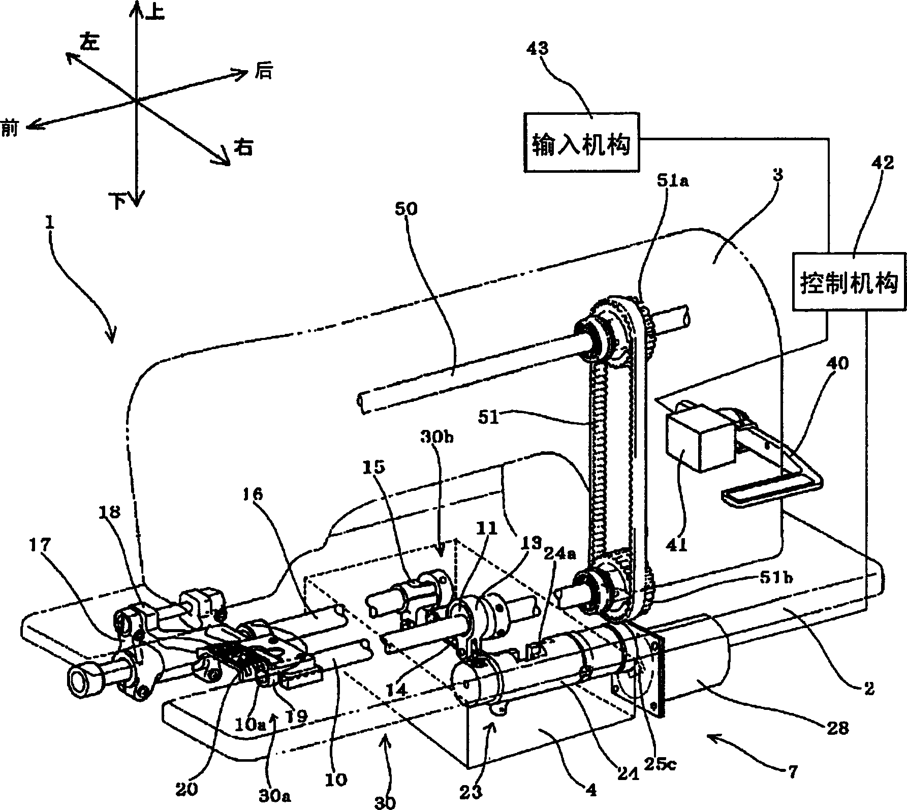
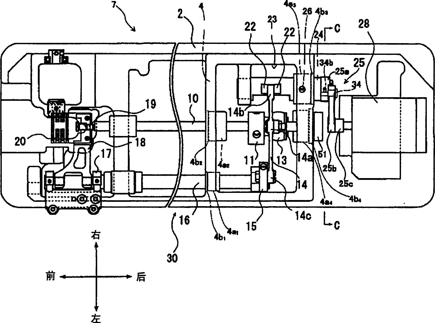
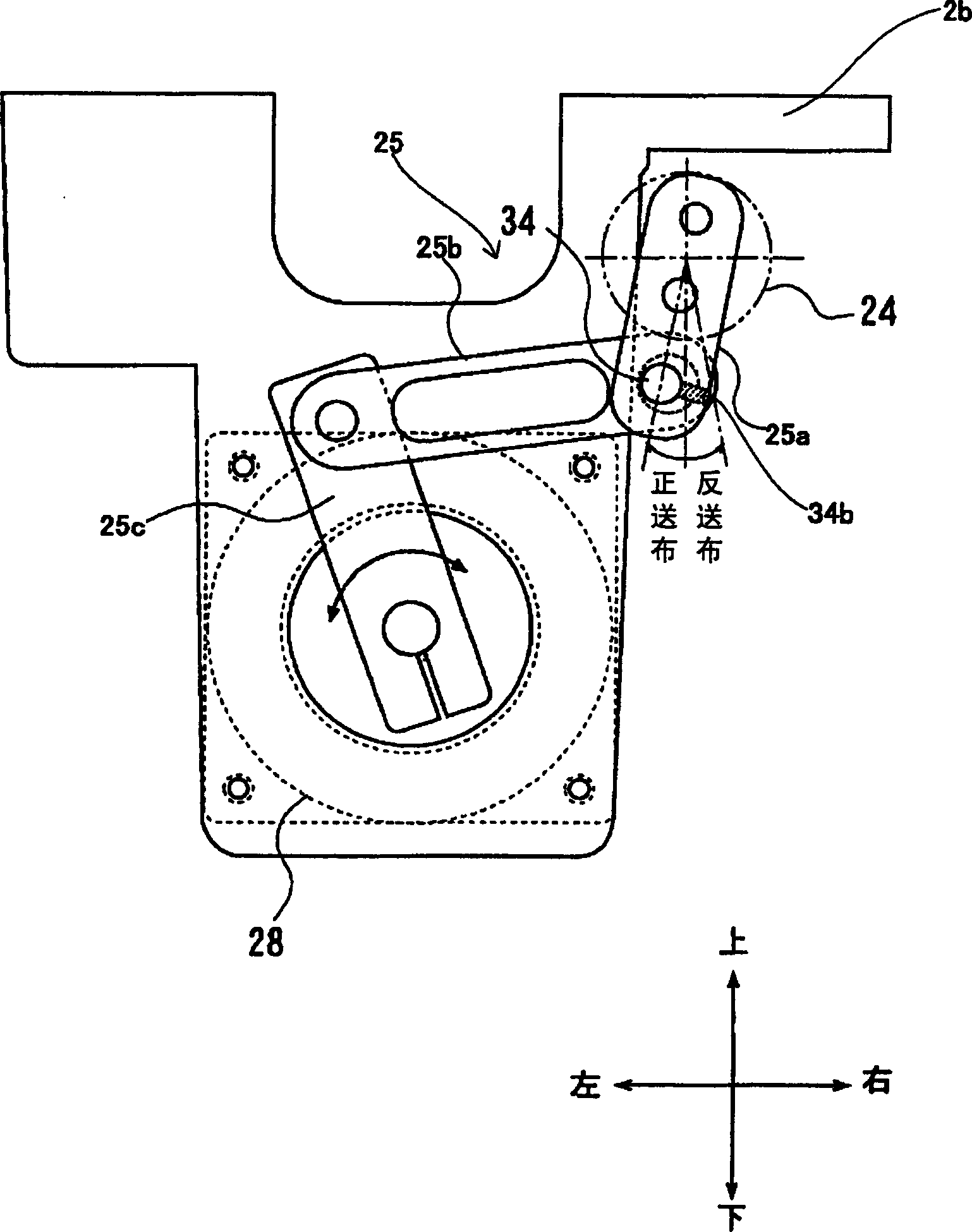
[0051] Hereinafter, specific embodiments of the cloth feeding device of the present invention will be described with reference to the drawings. In addition, in figure 1 , 2 In the structure shown, the feed dog 20, the feed table 18, the feed transfer mechanism 30 (the upper and lower feed mechanism 30a (the lower shaft eccentric part 10a, the upper and lower feed link 19, etc.), the horizontal feed mechanism 30b (horizontal Feed cam 11, horizontal feed lever 13, horizontal feed connecting rod 14, horizontal feed arm 15, horizontal feed shaft 16, (slider 22, groove 24a, etc.), feed amount changing mechanism 23 (feed Adjusting body 24, slider 22, etc.) is almost the same as the conventional structure, so its detailed description is omitted.

[0052] exist figure 1 , 2 Among them, the main shaft 50 extending in the front-back direction is rotatably supported on the sewing machine head, and the main shaft 50 is rotated in conjunction with a drive source (not shown), and is t...


PUM


Abstract

A horizontal feed mechanism 30b and a feed distance change means 23 of a cloth feeder 7 is provided in a closed lubricating chamber 4 separated from the outside. A pulse motor (a drive means) 28 actuating the feed distance change means 23 to change the feed distance is connected to a feed adjusting body 24 of the feed distance change means 23 via a link mechanism 25 and is fixed to the lower part of a sewing machine bed 2 outside the lubricating chamber 4. To provide a feeder capable of quietly changing an accurate feed distance even in a high-speed sewing time.

Description

technical field [0001] The invention relates to a cloth feeding device of a sewing machine which conveys a sewing product through a cloth feeding dog. Background technique [0002] In the cloth feed device that feeds the sewn product through the feed dog, there are, for example, the following methods for changing the cloth feed transmission mechanism, the cloth feed amount of one pitch, or the cloth feed direction. Figure 5 , 6 The cloth feed device 70 and the like of the shown cloth feed transmission mechanism 30 and the cloth feed amount changing mechanism 230 are well known. exist Figure 5 Among them, the free end side of the sewing machine head 3 is taken as the front, the upright longitudinal body side is taken as the rear, the front of the cloth feeding (normal feeding) direction is taken as the left, and the direction of the cloth feeding (normal feeding) is taken as the front. Front is right. [0003] Here, refer to Figure 5 , 6 The configuration of the cloth f...

Claims


Application Information

Patent Timeline
Patent Type & Authority Applications(China)
IPC IPC(8): D05B27/02D05B27/22
CPCD05B27/22D05B27/02B21C25/10
Inventor 岩田寿之后藤圣司
Owner JUKI CORP
Why Eureka
Try Eureka