Device for closing a container and removing a fluid product

A container and fluid technology, applied in the field of fluid product devices, can solve problems such as damage, hindering the precise adjustment of fluid flow rate, and openings that cannot be easily positioned relative to each other

Inactive Publication Date: 2004-12-22
BERICAP
View PDF1 Cites 4 Cited by
  • Summary
  • Abstract
  • Description
  • Claims
  • Application Information

AI Technical Summary

Problems solved by technology

[0015] On the one hand, this causes the latch flange to wear out due to friction between the two pieces when the movable piece is in the most pushed-in position
Therefore, holding the movable member in the withdrawn position risks damage
[0016] On the other hand, when the movable member is in the withdrawn position, the free rotation of the movable member prevents the openings in the two members from being easily positioned relative to each other, preventing precise adjustment of the flow rate of the poured fluid

Method used


Image

  • Device for closing a container and removing a fluid product
  • Device for closing a container and removing a fluid product
  • Device for closing a container and removing a fluid product

Examples


Embodiment Construction

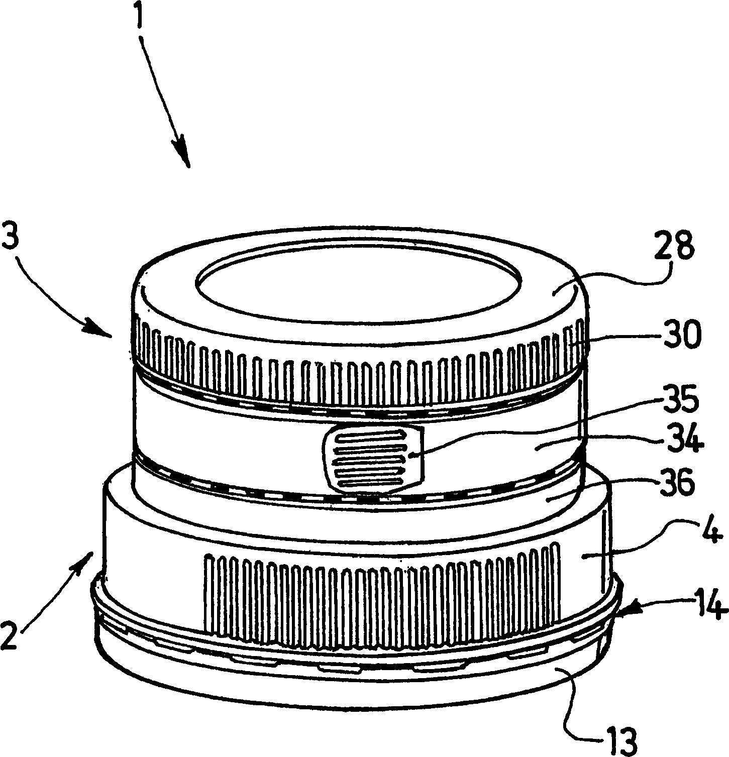
[0052] The processor 1 according to the invention is used for blocking containers (not shown), such as plastic bottles, and for extracting fluid products contained in said containers.

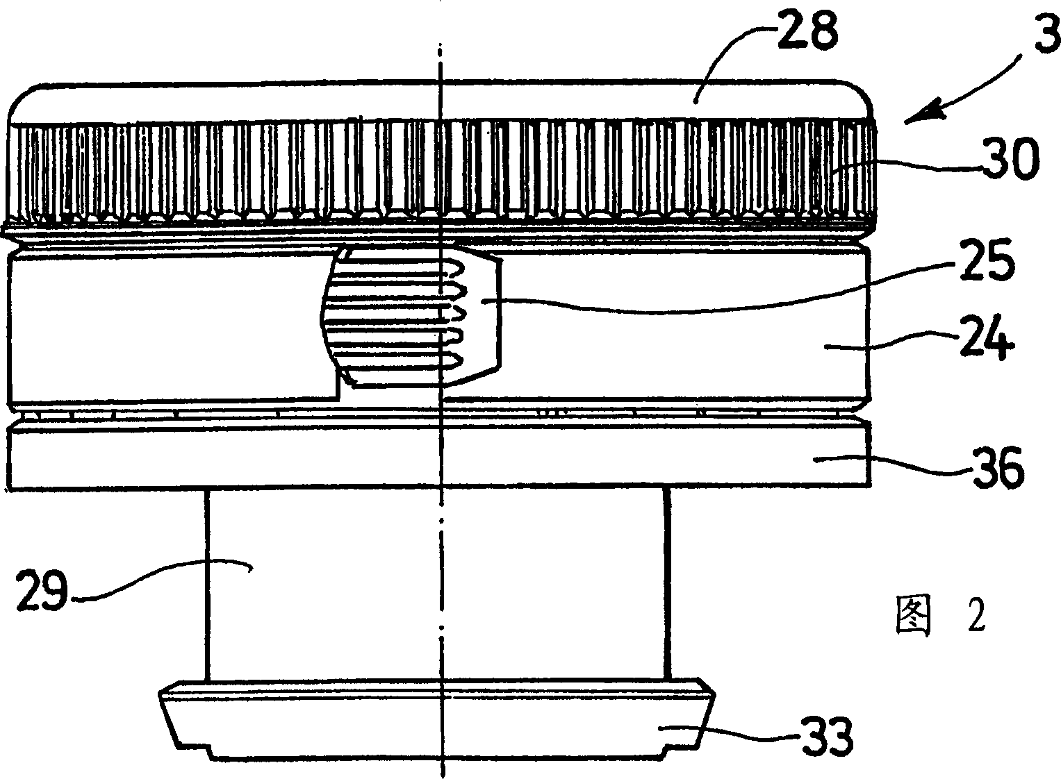
[0053] The processor 1 comprises a fixed part 2 and a movable part 3, wherein the fixed part is fixed to the neck of said container, the movable part and the fixed part 2 cooperate to control and regulate the withdrawal of the fluid contained in the container operate.

[0054] Throughout the description, the terms "upper" and "lower" are used for simplicity, taking into account that the axis of the device is substantially vertical, with the fixed part 2 positioned above the movable part 3 . It should be understood, however, that the device can be located anywhere in space.

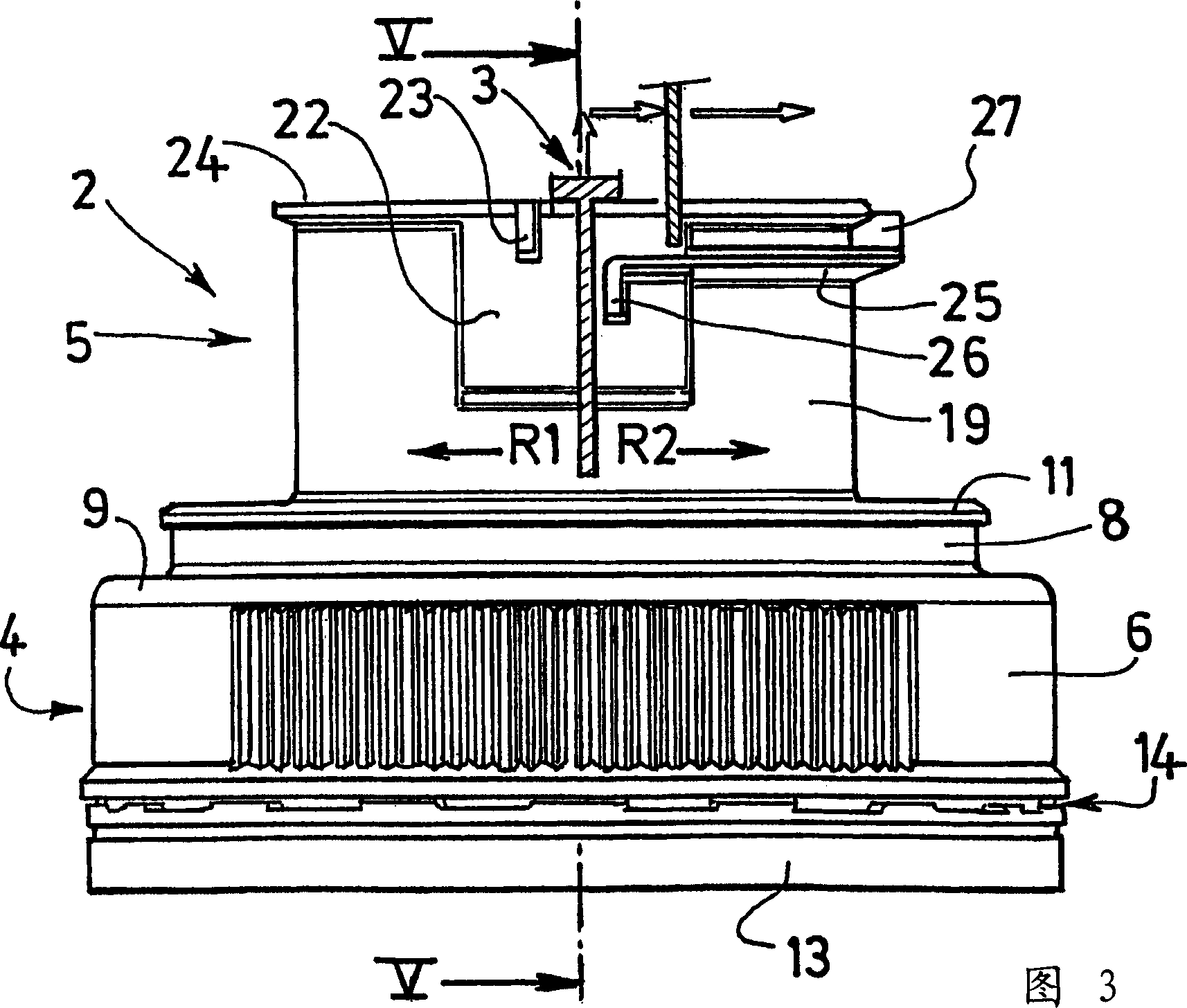
[0055] The fixing 2 comprises a fixing part 4 fixed to the container and a substantially cylindrical pouring part 5 which continues said fixing part 4 towards the outside of the container.

[0056] The fixing part 4 compr...


PUM


Abstract

The device comprises: a piece fixed to the container, having a lateral fluid output opening and a passage allowing the entry of air; a movable piece comprising a tube having a lateral fluid output opening, the tube being movable rotationally in the fixed piece and in axial translation between a maximum pushing-in position and an extraction position where the lateral openings can be brought into coincidence by rotation of the movable piece. The movable piece comprises an internal skirt making it possible to channel the fluid towards the output opening in order to prevent leakages through the air entry passage. The fixed piece comprises means for guiding the displacement of the movable piece with respect to the fixed piece from the maximum pushing-in position to the extraction position with coincidence of the openings.

Description

technical field [0001] The invention relates to a device for blocking a container and discharging a fluid product contained in said container. Background technique [0002] The above-mentioned device is known, in particular from the applicant's patent EP0815030. [0003] Such devices usually include: [0004] - a fixing piece comprising a portion for fixing to the container and a substantially cylindrical pouring portion continuing said fixing portion towards the outside of the container, the pouring portion being open at both axial ends thereof, and having a lateral fluid discharge opening and defining a path that allows air to enter the device during pouring of the fluid; [0005] - a movable member comprising a transverse end wall from which protrudes in the same direction on the one hand a generally cylindrical tube and on the other hand an outer skirt, the tube being open at its axial free end And having at least one lateral fluid discharge opening, the outer skirt e...

Claims


Application Information

Patent Timeline
Patent Type & Authority Applications(China)
IPC IPC(8): B65D47/26B65D47/28B65D47/32
CPCB65D2101/0038B65D47/283B65D47/32B65D47/263B65D2401/25
Inventor 菲利普·努斯鲍姆弗雷德里克·格拉尼尔安东尼奥·朱贝尼克拉雷特奥里奥尔·阿兰格雷西亚
Owner BERICAP
Why Eureka
Try Eureka