
Display panel driver device

A technology for driving devices and display panels, applied in static indicators, televisions, instruments, etc., can solve the problems of good comprehensive effect and deterioration of image quality.

Inactive Publication Date: 2005-02-09
PIONEER CORP
View PDF2 Cites 3 Cited by
  • Summary
  • Abstract
  • Description
  • Claims
  • Application Information

AI Technical Summary

Problems solved by technology

This means that the observed overall effect cannot be expected to be good, and the image quality deteriorates

Method used


Image

  • Display panel driver device
  • Display panel driver device
  • Display panel driver device

Examples


Embodiment Construction

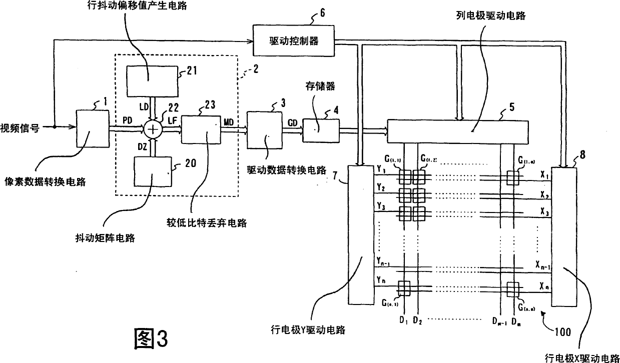
[0027] A description will now be provided of a driving apparatus for driving a plasma display panel (PDP) according to a driving method of one embodiment of the present invention with reference to FIGS. 3 to 14. Referring to FIG.

[0028] Referring to FIG. 3, the PDP 100 includes a front substrate (not shown) serving as a display surface, and a rear substrate (not shown) positioned opposite to the front substrate. A discharge space filled with a discharge gas is defined between the front-side substrate and the rear-side substrate. Strip row electrodesX 1 to x n and row electrode Y 1 to Y n They are arranged parallel to each other and arranged on the front substrate. The strip-shaped column electrodes D1 to Dm are intersected with the row electrodes and arranged on the rear substrate. Row electrode X 1 to x n and Y 1 to Y n n pairs of row electrodes X are arranged for the first to nth display rows of the PDP 100 i and Y i Sure. A discharge cell G serving as a pixel ...


PUM


Abstract

A driver device for a display panel. Pixel cells are arranged on respective display lines of the display panel. Each N adjacent display lines makes one display line group. N is an integer of two or more. The pixels in each display line group are driven to emit light at different patterns. One of the M dither patterns is selected sequentially and in predetermined periods, and the selected dither pattern is used. M is less than N. In the dither processing, N different weighting values are allocated to the N display lines in the display line group, respectively.

Description

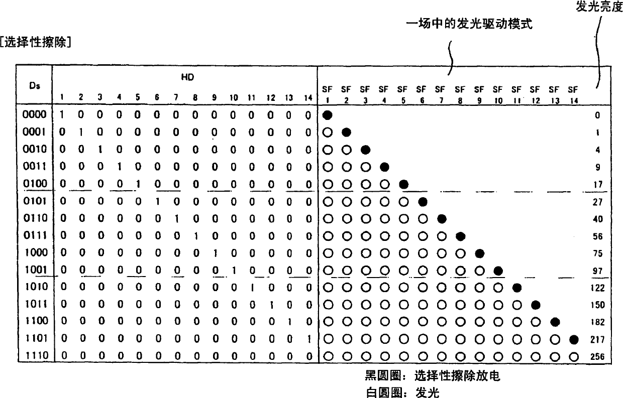
technical field [0001] The invention relates to a driving device for a display panel having pixel units serving as pixels, the pixel units being arranged on individual display lines of the display panel. Background technique [0002] Recently, in the field of two-dimensional image display panels, a plasma display panel (hereinafter referred to as 'PDP') has attracted attention, in which a plurality of discharge cells are arranged in a matrix form. The subfield method is known as a driving method for displaying an image corresponding to a video input signal on a PDP. The subfield method drives to divide a single field display period into multiple subfields, and makes each discharge unit selectively discharge and emit light in each subfield according to the brightness level represented by the video input signal. Thus, an intermediate or gray scale brightness corresponding to all light periods within a single field period is perceived. [0003] Fig. 1 of the accompanying draw...

Claims


Application Information

Patent Timeline
IPC IPC(8): H04N5/66G09G3/10G09G3/20G09G3/28G09G3/288G09G3/298
CPCG09G3/2025G09G2320/0266G09G3/2935G09G2310/0218G09G2320/0261G09G3/204G09G3/2077G09G3/2055G09G3/296
Inventor 铃木雅博上山口润重田哲也本田广史长久保哲朗
Owner PIONEER CORP
Learn More