Optical disc drive

An optical disc drive, optical disc technology, applied to instruments, transducing head devices, data recording and other directions, can solve problems such as disc 60 detachment

Inactive Publication Date: 2005-02-09
TOSHIBA SAMSUNG STORAGE TECH KOREA CORP
View PDF2 Cites 1 Cited by
  • Summary
  • Abstract
  • Description
  • Claims
  • Application Information

AI Technical Summary

Problems solved by technology

Therefore, there is a very high probability that the optical disc 60 will come off

Method used


Image

  • Optical disc drive
  • Optical disc drive
  • Optical disc drive

Examples


Embodiment Construction

[0036] Reference will now be made in detail to the detailed description of the invention and examples illustrated in the accompanying drawings, wherein like reference numerals refer to like elements throughout. Hereinafter, the present invention will be explained by describing specific embodiments with reference to the figures.

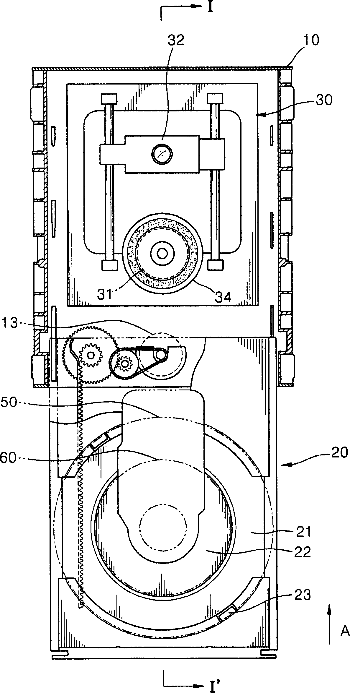
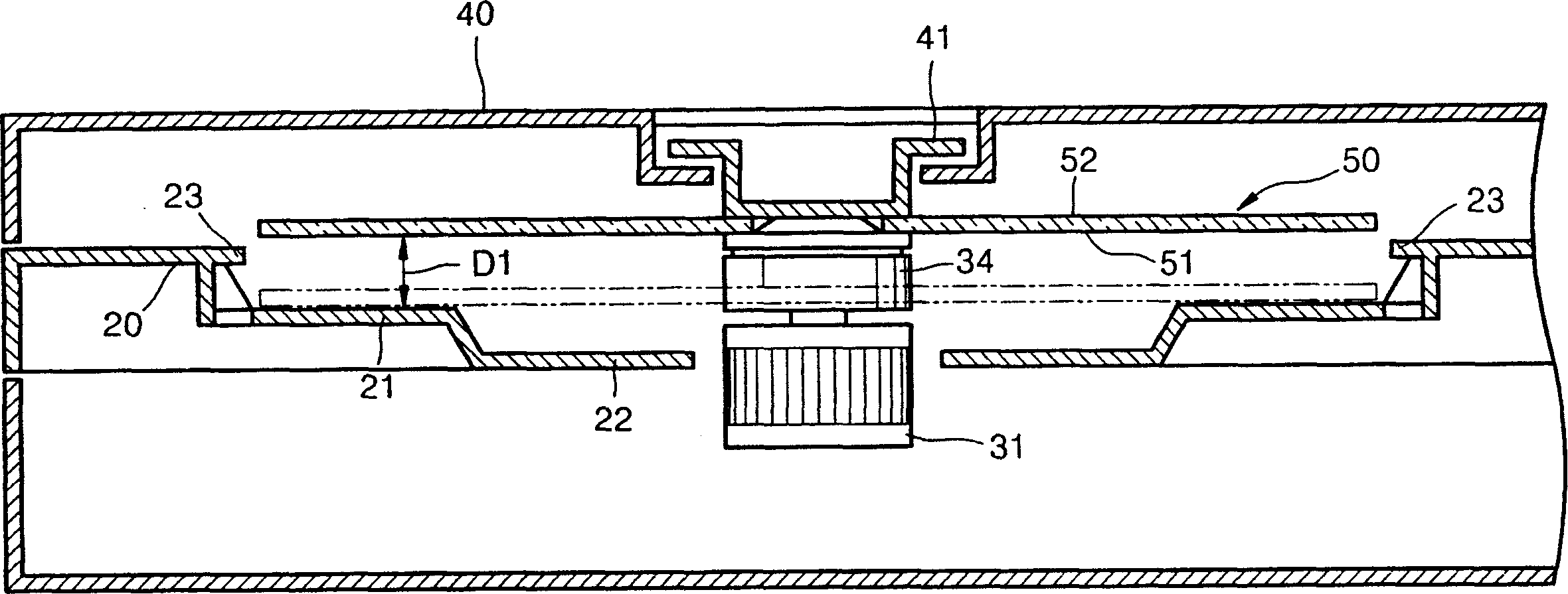
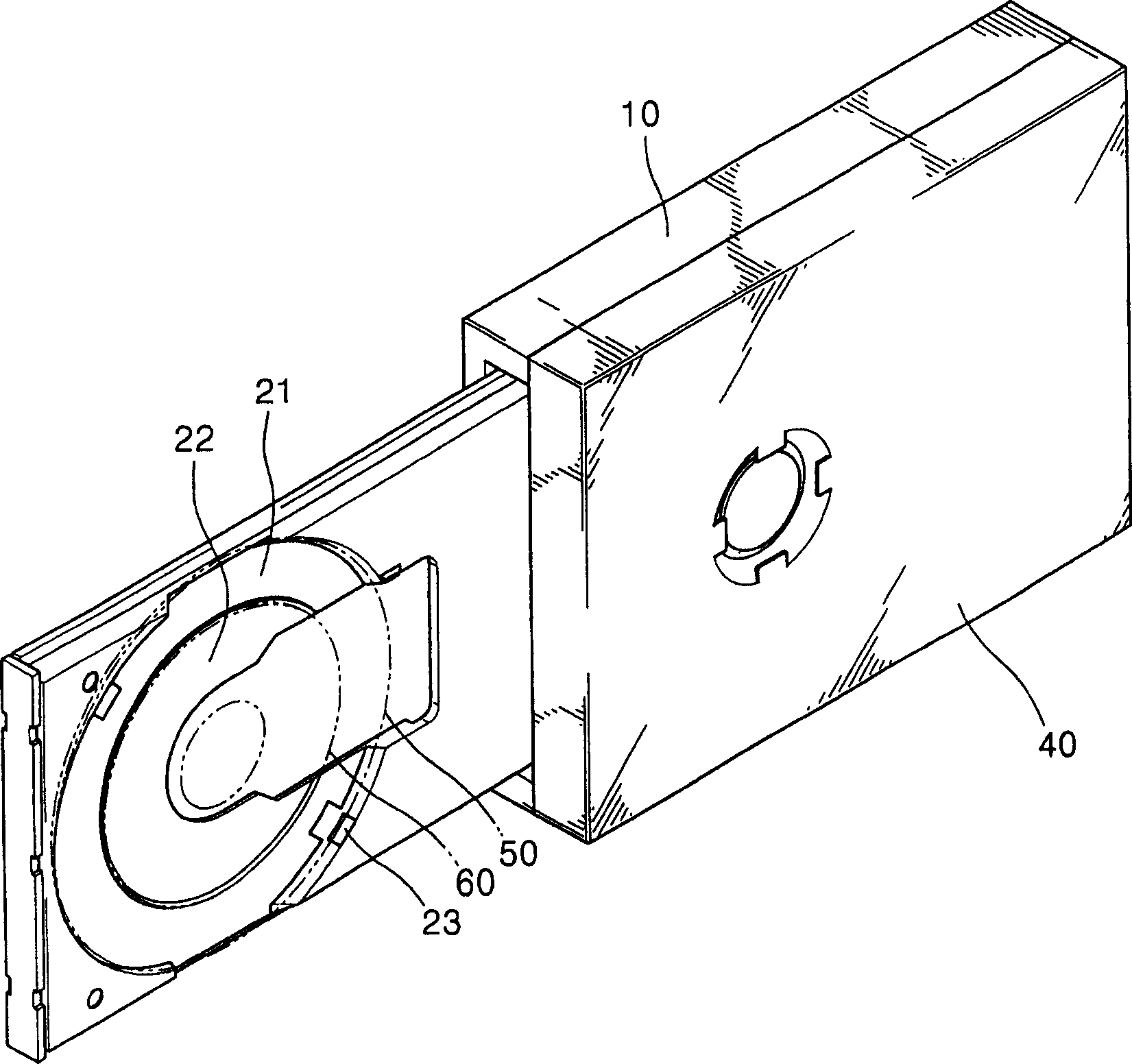
[0037] Figure 5is an exploded perspective view of an optical disc drive according to an embodiment of the present invention. The first frame 110, the second frame 120 facing the first frame 110, and the tray 130 are shown. The spindle motor 160 rotates the optical disc 200 , and the optical pickup 150 approaches the optical disc 200 and writes and / or reproduces information on the optical disc 200 . The loading motor 170 loads / unloads the tray 130 . The loading motor 170 turns the gear 171 . Reference numeral 300 is a clamping mechanism.

[0038] A loading motor 170 and a pinion 171 are installed in the first frame 110 . In addition, the cam mem...


PUM


Abstract

An optical disc drive including a clamping mechanism, which faces a turntable, supports a surface of a disc, and is rotated. The clamping mechanism includes a clamper, which has access to the disc by a magnetic force when a spindle motor has access to the disc so that the disc is not deviated from a mounting portion when clamping is not completely performed, and a return member, which allows the damper to be spaced apart from the disc as the spindle motor is spaced apart from the disc.

Description

technical field [0001] The present invention relates to an optical disc drive, and more particularly, to an optical disc drive capable of being installed horizontally and vertically. [0002] This application claims the benefit of Korean Patent Application No. 2003-46328 filed on July 9, 2003 and Korean Patent Application No. 2003-55212 filed on August 9, 2003 at the Korean Intellectual Property Office, which disclose The contents are incorporated herein by reference. Background technique [0003] An optical disc drive is generally a device that writes or reads information by emitting light onto an optical medium (hereinafter referred to as an optical disc) such as a compact disc (CD) or a digital versatile disc (DVD). [0004] figure 1 is a floor plan showing a conventional optical drive. figure 2 is along figure 1 The sectional view taken by the line I-I' in. [0005] refer to figure 1 with 2 , the tray 20 is slidably mounted on the frame 10 . The frame 10 include...

Claims


Application Information

Patent Timeline
IPC IPC(8): G11B17/056G11B17/028G11B17/04
CPCG11B17/0284G11B17/056
Inventor 金忠雄赵珌济李珪炯许荣佑
Owner TOSHIBA SAMSUNG STORAGE TECH KOREA CORP
Why Eureka
Try Eureka