Automatic motor-driven blender cup with a leak-free magnetic stirring apparatus

a technology of magnetic stirring and motor-driven blender, which is applied in the direction of rotary stirring mixer, transportation and packaging, mixing, etc., can solve the problems of mass consumers having to bear the extra cost, the total malfunction of the blender cup, and the increase of consumer expenditure, so as to achieve better stirring speed and uniform blending effect.

Inactive Publication Date: 2008-01-01
CAI YING LIN
View PDF19 Cites 95 Cited by
  • Summary
  • Abstract
  • Description
  • Claims
  • Application Information

AI Technical Summary

Benefits of technology

[0005]The main object of the present invention is to provide an automatic motor-driven blender cup with stirring apparatus of leakage-free comprising a blender cup, an internal chamber, a mounting frame, a stirring shaft, a magnetic disk and a motor with a dry battery; Wherein, said mounting frame and stirring shaft are disposed at the central position of the inside base wall of said blender cup; said magnetic disk is correspondently fixed inside of the bottom space of said internal chamber with central axial line in alignment with that of said stirring shaft without any physical link or contact each other; The stirring propeller on said stirring shaft will be magnetically inducted by said corresponding magnetic disk to simultaneously rotate in said internal chamber when said magnetic disk is driven by the output shaft of said motor; Thus, not only the stirring effect of liquid or fluid in said internal chamber can be achieved, but also said liquid or fluid can be prevented from leakage and seepage out of the base wall of said blender cup so as to insure said motor free from premature defectively damage due to moisture erosion.
[0006]The another object of the present invention is to provide an automatic motor-driven blender cup with stirring apparatus of leakage-free, wherein more than two sets of the mounting frames and stirring shafts are disposed in the bottom portion of said internal chamber including additional multiple gear set coupled with said output shaft of the motor, so that multiple sets of magnetic disks with magnetic inducted stirring propellers can be driven by one original motor in order to have better stirring speed and uniformity of blending effect.

Problems solved by technology

However, the same serious drawback exists in both of conventional motor-driven blender cup aforesaid or others in commercial availability: the output shaft 6 of the motor M must pass through the bushing 5 in the base wall under said internal chamber 2 of said blender cup 1; Hence a gap δ will be formed at the contact portion between the circumference of said output shaft 6 and the inner wall of said bushing 5 due to mutual friction (as shown in the magnified view of the FIG. 1), so that the liquid or fluid W to be stirred and blended in said internal chamber 2 will leak and seep into the bottom portion of said blender cup 1 via said gap δ; Before long, it will cause motor M, dry battery B and start switch 7 short circuit or defectively damaged, and result in total malfunction of the blender cup; That is the insoluble drawback and problem exists in all conventional motor-driven blender cup of commercial availability.
Moreover, subject to the inevitable moisture leakage and seepage issue aforesaid, the manufacturer is unable to equip more than two set of propeller 4 in the internal chamber 2 to avoid augmenting the drawback of moisture leakage and seepage; Therefore, the only way for all those current motor-driven blender cups of commercial availability to meet the requirement of better well-mixed is to increase the stirring time with unavoidable side-effect of expediting depletion of the dry battery B relatively, which resulting in more expenditure for consumers to frequently replace said dry battery B; Thus, the mass consumers have to bear the extra cost due to inferior product from careless and unenterprising contrivance of the undutiful manufacturers seems senseless and unreasonable.

Method used


Image

  • Automatic motor-driven blender cup with a leak-free magnetic stirring apparatus
  • Automatic motor-driven blender cup with a leak-free magnetic stirring apparatus
  • Automatic motor-driven blender cup with a leak-free magnetic stirring apparatus

Examples


Embodiment Construction

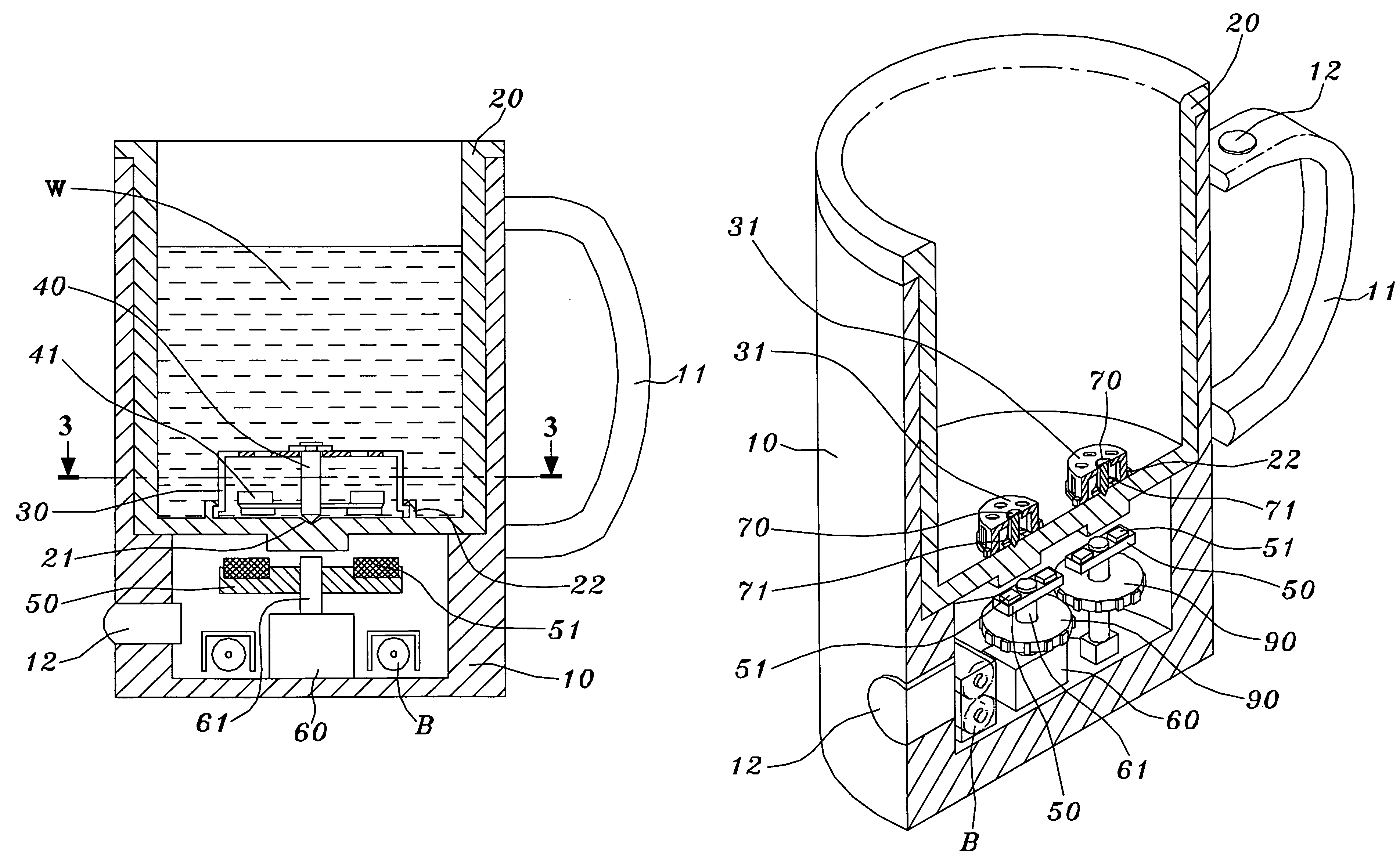
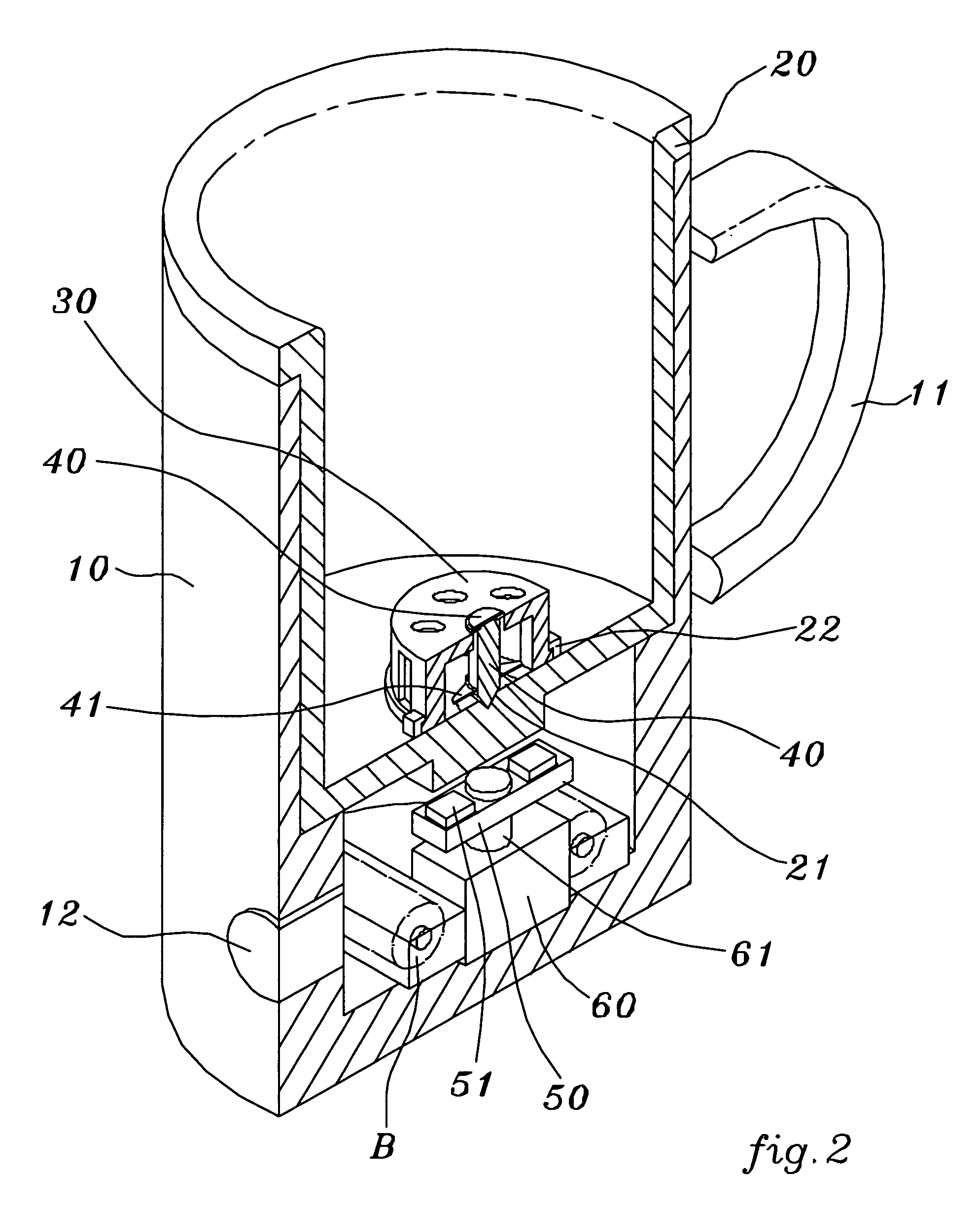
[0015]Referring to FIGS. 2 through 4, an automatic motor-driven blender cup with a leakage-free stirring apparatus according to a preferred embodiment of the present invention, comprises a blender cup 10, an internal chamber 20, a mounting frame 30, a stirring shaft 40, a magnetic disk 50 and a motor 60 with a dry battery B; Wherein, said blender cup 10 includes an internal chamber 20 formed upward with opening on the top side and a handle 3 disposed on the peripheral surface together with a push button 12; said internal chamber 20 is a hollow container having a miniature bearing notch 21 indented in the center of the inside bottom with some upstanding clasps 22 arranged and jutted around said bearing notch 21; said mounting frame 30 is a opening downward cannular frame with flange at the bottom rim such that being securely buckled by all said upstanding clasps 22 on said internal chamber 20; said stirring shaft 40 is formed with a cone-shaped front tip downward to be jointly inset ...


PUM


Abstract

An automatic motor-driven blender cup with a leakage-free stirring apparatus includes a blender cup, an internal chamber, a mounting frame, a stirring shaft, a magnetic disk and a motor with a dry battery; wherein, said mounting frame and stirring shaft are disposed at the central position of the inside base wall of said blender cup; said magnetic disk is correspondently fixed inside of the bottom space of said internal chamber with central axial line in alignment with that of said stirring shaft without any physical link or contact each other; the stirring propeller on said stirring shaft will be magnetically inducted by said corresponding magnetic disk to simultaneously rotate in said internal chamber when said magnetic disk is driven by the output shaft of said motor; thus, not only the stirring effect of liquid or fluid in said internal chamber can be achieved, but also said liquid or fluid can be prevented from leakage and seepage out of the base wall of said blender cup so as to insure said motor free from premature defectively damage due to moisture erosion.

Description

FIELD OF THE PRESENT INVENTION[0001]The present invention relates to the blender cup, particularly for the household or outdoor blender cup including motor-driven stirring function to rotationally stir liquid in the cup; basing mainly on the magnetic force over space so that both of the physical isolated propeller and motor output shaft can be interactively coupled to overcome the problem in liquid leakage from cup seeping into motor along output shaft gap, which always happens in the conventional blender cup and results in the drawback of shortening the service life in premature defectively damage due to moisture erosion of the blender cup.BACKGROUND OF THE INVENTION[0002]Currently, the structure of known conventional motor-driven stirring blender cup for the household or outdoor use is of somewhat same as disclosed in the U.S. Pat. Nos. 4,435,084 and 5,639,161 and shown in the FIG. 1. All of which, an output shaft 6 driven by the motor M is disposed in the lower section of the ble...

Claims


Application Information

Patent Timeline
Patent Type & Authority Patents(United States)
IPC IPC(8): B01F13/08
CPCA47J43/0465A47J43/0727B01F7/1695B01F13/002B01F13/0827B01F13/0863B01F2215/0026B01F27/88B01F33/5011B01F33/453B01F33/4534B01F2101/1805
Inventor CAI, YING LIN
Owner CAI YING LIN
Why Eureka
Try Eureka