

Magnetic hinge apparatus
a magnetic hinge and hinge technology, applied in the field of hinge apparatuses, can solve the problems of shortening the utility life of the hinge apparatus, suffering from several drawbacks of the conventional hinge design, etc., and achieve the effect of overcompensating the drawback of elasticity decay of the conventional hing
- Summary
- Abstract
- Description
- Claims
- Application Information
AI Technical Summary
Benefits of technology
Problems solved by technology
Method used
Image

Examples
first embodiment
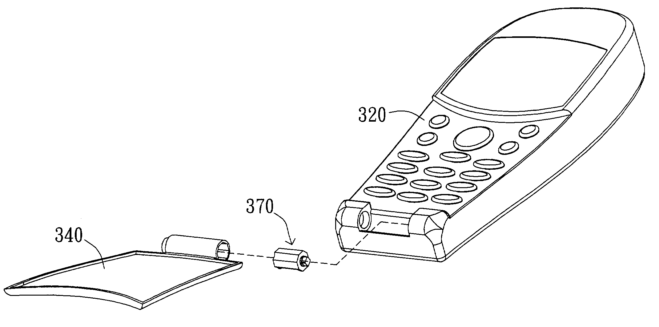
[0030]FIG. 3 is a drawing of a disassembled phone body, a flip cover, and a magnetic hinge according to the first embodiment of the invention. The phone body 320 and the flip cover 340 are connected by the magnetic hinge 370. While the flip cover 340 is rotated, the hinge housing is simultaneously rotated around the hinge shaft. The magnetic hinge 370 allows the pivoting of the flip cover 340 on the phone body 320, and the flip cover 340 can be maintained at the open or close position. FIG. 4A is a side view of the magnetic hinge of FIG. 3 while the flip cover is maintained at the fully-closed position. The magnetic hinge 370 mainly includes a bingo housing 410 and a hinge shaft 450, wherein the hinge housing 410 rotates around the hinge shaft 450. In the practical application, the hinge housing 410 can be connected to the flip cover 340, while the hinge shaft 450 can be connected to the phone body 320. After assembly, the rotation of the flip cover 340 can be performed. FIG. 4B is ...
second embodiment
[0038]The structure of the rotatable magnetic device and the immobilized magnetic device can be simplified. The second embodiment utilizing two magnets having the same polarity also achieves the objective of the invention. FIG. 9 is a schematic diagram of the immobilized magnetic device and the rotatable magnetic device according to the second embodiment of the invention. The immobilized magnetic device, such as the magnet 91, is assembled to the housing of the magnetic hinge apparatus. The rotatable magnetic device, such as the magnet 92, is assembled on the hinge shaft of the magnetic hinge apparatus. The magnets 91 and 92 have the same polarity (such as a north magnetic pole) and are set at the opposite sides. Also, the hinge shaft and the housing are connected to the phone body and the flip cover of the cellular phone, respectively. The hinge housing is simultaneously rotated around the hinge shaft while the flip cover is rotated. The magnetic hinge allows the pivoting of the fl...
third embodiment
[0039]FIG. 10A is a drawing of the disassembled magnetic hinge according to the third embodiment of the invention. The rotatable magnetic devices 1200 and 1400 and the immobilized magnetic device 1300 are assembled on the hinge shaft 1100. The rotatable magnetic device signifies that the relative motion can be generated between the hinge housing and the rotatable magnetic device. The immobilized magnetic device signifies that the relative motion cannot be generated between the hinge housing and the immobilized magnetic device. After assembly of each component, the hinge shaft 1100 is inserted into the cavity of the hinge housing 1500. The hinge housing 1500 is simultaneously rotated around the hinge shaft 1100 while the flip cover is opened; meanwhile, the immobilized magnetic device 1300 secured to the hinge housing 1500 is rotated relatively to the rotatable magnetic devices 1200 and 1400. By the suitable arrangement of magnetic poles of the hinge components, the hinge shaft 1100 ...
PUM
 Abstract
Description
Claims
Application Information