

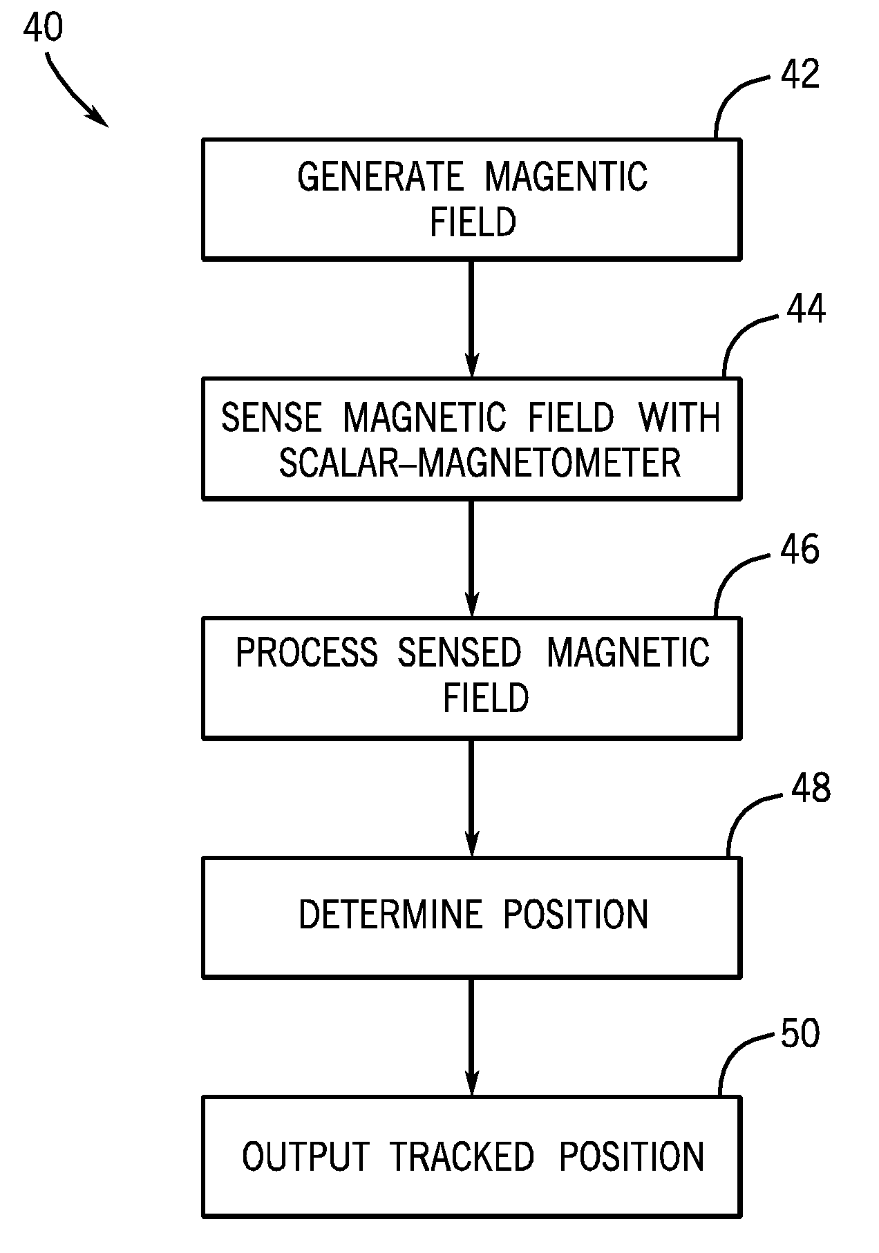
Electromagnetic tracking employing scalar-magnetometer
a scalar magnetometer and electromagnetometer technology, applied in the field of electromagnetometer employing scalar magnetometer, can solve problems such as reducing the overall accuracy of the tracking system
- Summary
- Abstract
- Description
- Claims
- Application Information
AI Technical Summary
Problems solved by technology
Method used
Image

Examples
Embodiment Construction
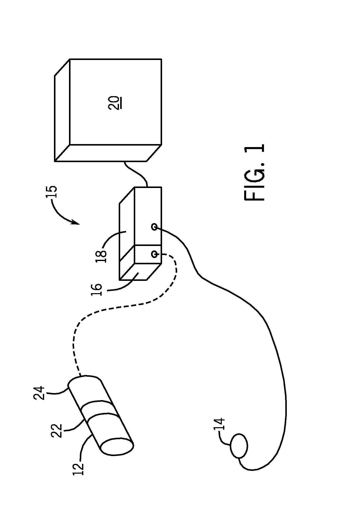
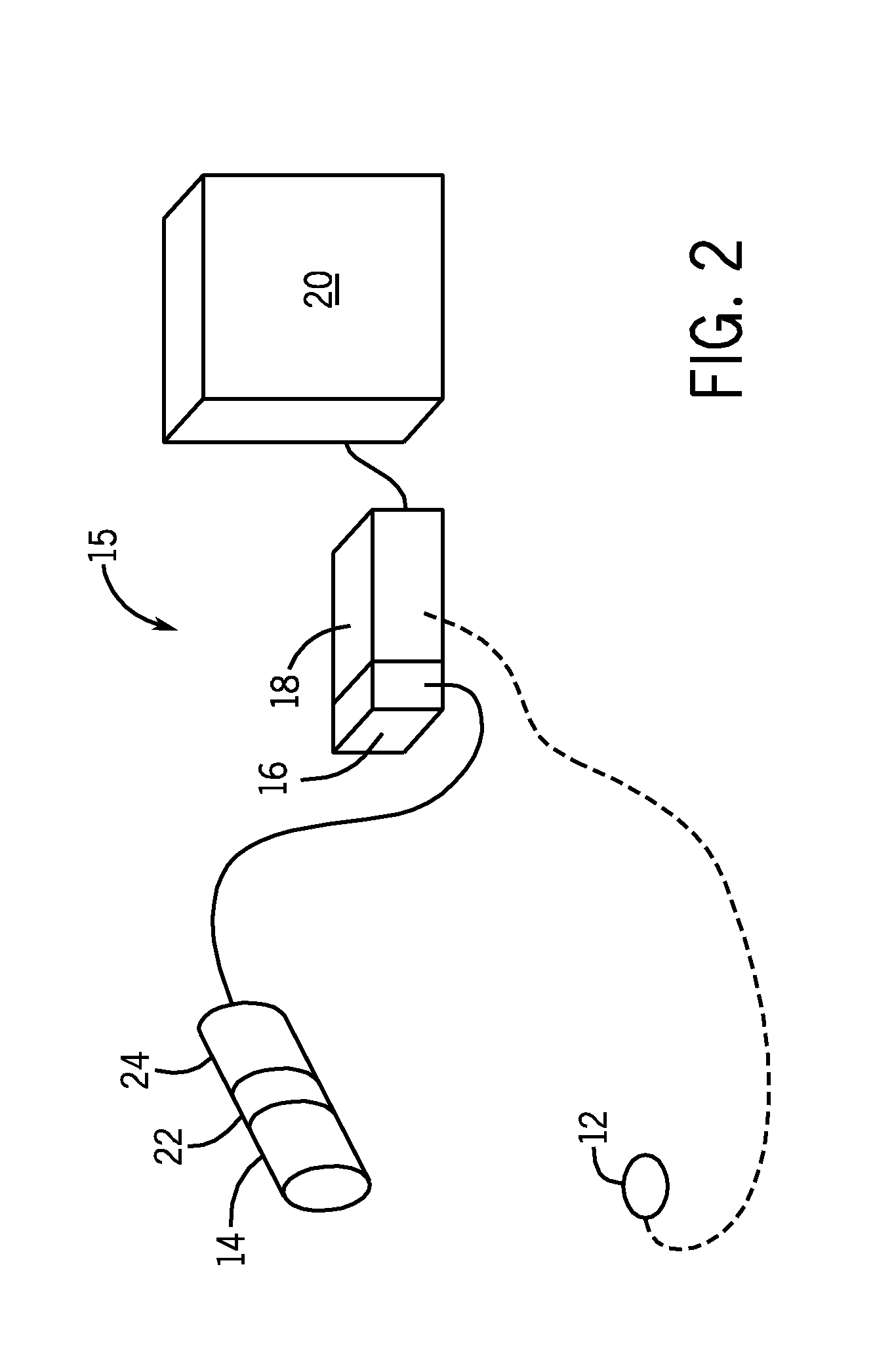
[0019]FIG. 1 illustrates a tracking system 10 in accordance with an embodiment of the present technique. The tracking system 10 includes at least one transmitter 12, at least one receiver 14, tracker electronics 15, a drive unit 16, a processor 18, a user interface 20, a current source 22, and an instrument 24.
[0020]The transmitter 12 includes a magnetic field source that can be employed to generate a magnetic field. For instance, the at least one transmitter 12 may include an electromagnet that generates the desired magnetic field (e.g., radio frequency (RF) magnetic field). The magnetic field may be of sufficient magnitude to be sensed by a complementary device, such as the at least one receiver 14. In one embodiment, the at least one transmitter 12 includes a single dipole coil. For example, the at least one transmitter 12 may include a single dipole coil that is about 8 mm long and about 1.7 mm in diameter, with 7700 turns of American Wire Gauge (AWG) wire formed around a ferrom...
PUM
 Abstract
Description
Claims
Application Information