Reducing effects of magnetic and electromagnetic fields on an implant's magnet and/or electronics

a technology applied in the field of magnetic switch, can solve the problems of potential dangerous effect, low voltage, and partial demagnetization of the implanted magnet, and achieve the effect of reducing the effect of magnetic field and electromagnetic field on the implanted magnet and/or electronics

Inactive Publication Date: 2005-01-04
MED EL ELEKTROMEDIZINISCHE GERAETE GMBH
View PDF11 Cites 95 Cited by
  • Summary
  • Abstract
  • Description
  • Claims
  • Application Information

AI Technical Summary

Benefits of technology

In related embodiments of the invention, at least one recessed region is positioned at a magnetic pole. The magnet may include a north pole and a south pole, the at least one recessed region positioned between the north pole and the south pole. The switch may be part of a cochlear implant, and may include a first coil adapted to be electromagnetically coupled with a second coil of an external device. The switch may provides overvoltage protection as a function of an orientation of the external magnetic field.

Problems solved by technology

Secondly, due to the external magnetic field, the implanted magnet may become partly demagnetized and may not be strong enough after the MRI field exposure to hold the external part in place.
Another potentially dangerous effect may occur when RF pulses emitted by the MRI unit induce voltages in the implant coil, implant circuit and / or electrode circuit.
These voltages may generate unwanted stimulation, especially in implants with analog electronic circuitry.
Additionally, over-voltages may be generated which could destroy the implant electronics.
Still other adverse effects can occur when a patient with a cochlear implant undergoes an MRI examination.
These artifacts are caused by the local magnetic field of the implanted magnet, which distorts the homogeneous MRI field.
However, this may exclude the patient from certain important diagnostic measures.
This requires two surgical interventions in order to perform a MRI examination, and makes it impossible to use the implant system during the healing phase of the incision.
Furthermore, the necessity to surgically remove the magnet before the MRI examination is a drawback especially in emergency cases and even could be forgotten in some cases.

Method used


Image

  • Reducing effects of magnetic and electromagnetic fields on an implant's magnet and/or electronics
  • Reducing effects of magnetic and electromagnetic fields on an implant's magnet and/or electronics
  • Reducing effects of magnetic and electromagnetic fields on an implant's magnet and/or electronics

Examples


Embodiment Construction

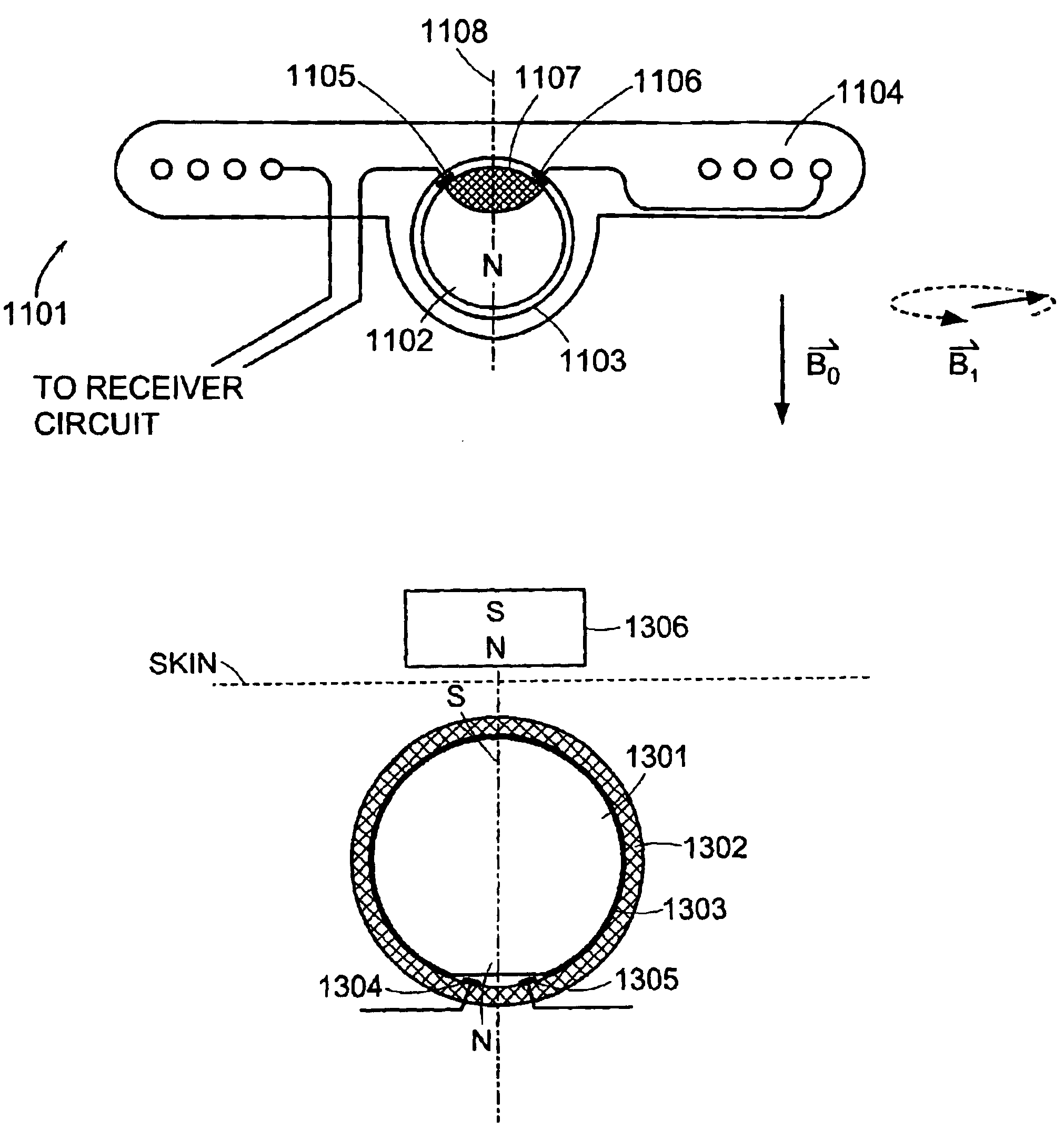
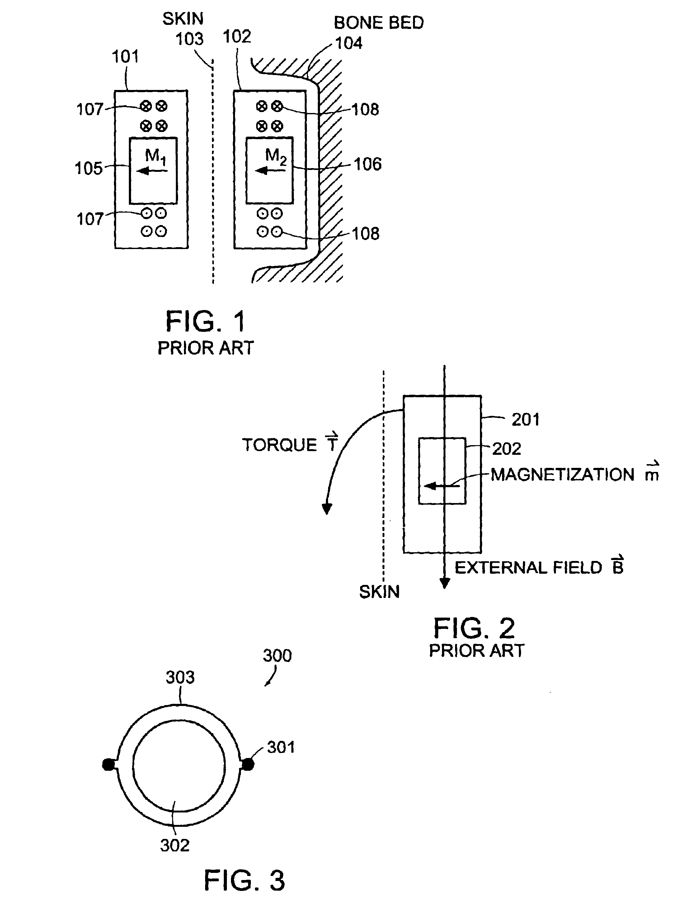
In illustrative embodiments of the invention, a method and device for reducing the effects of strong magnetic fields on an implanted magnet is presented. FIG. 3 shows an implant 300 for implementing an embodiment of the invention. The implant 300 includes a magnet 302 that is held in the implant 300 in such a way that the magnet 302 can turn into the direction of an externally applied magnet field. Thus, the magnet 302 does not experience any torque as a result of the external magnet field, nor will it become demagnetized.

The magnet 302 may be enclosed in a housing 303. The housing 303 allows the implanted magnet of whatever shape to turn, possibly with some restrictions, into the external magnetic field lines. In various embodiments of the invention, magnet 302 is hermetically encapsulated so as to prevent corrosion and / or leakage of the material into the body of the implant 300. Material used for the housing / encapsulation 303 may include, without limitation, titanium, nonmagnetic ...


PUM


Abstract

An implantable magnet that can freely turn in response to an external magnetic field, thus avoiding torque and demagnetization on the implantable magnet. The implantable magnet can be combined with an electric switching function depending on the orientation of an external magnetic field, thus protecting an implanted coil and/or implant electronics against induction of over-voltage or performing an electric switching function for other various purposes. The magnetic switch may further include, for example, a first switching contact and a second switching contact. A magnetically soft body that includes an electrically conductive surface is shiftable between a first position where the body is in simultaneous contact with the first and second switching contacts, and a second position where the body is out of contact with at least one of the first and second switching contacts. The body and the implantable magnet are positioned such that the body is shifted to one of the first position and the second position as a function of the external magnetic field resulting in a magnetic force between the magnet and the magnetically soft body.

Description

TECHNICAL FIELDThe present invention generally relates to a magnetic switch, and a method and apparatus for reducing the effect of magnetic fields and electromagnetic fields on an implanted magnet and electronics in an implant, respectively.BACKGROUND ARTPartly implantable systems may use magnets to hold internal and external pieces in place. For example, as shown in FIG. 1, a cochlear implant 102 located under the skin 103 and embedded in bone 104 typically include a first magnet 106 placed in the center of the implant 102, and a coil 108. An external part 101 includes a second magnet 105 that is positioned over the first magnet 106 such that the external part 101 is held against the implant 102 in an optimum position. By maintaining such a position, an external coil 107 positioned inside external part 101 can, via inductive coupling, transmit a transcutaneous signal and / or power to the coil 108 of implant 102.Upon a wearer of such a cochlear implant 102 having to undergo Magnetic ...

Claims


Application Information

Patent Timeline
Patent Type & Authority Patents(United States)
IPC IPC(8): A61N1/08H01H9/00A61N1/36A61N1/37A61N1/372A61N1/375A61N2/10H01H36/00H04R25/00
CPCA61N1/37H01H36/00H01H36/0073A61N1/3718H04L12/1868H04L12/1877H04L12/189H04W4/14H04W8/26
Inventor ZIMMERLING, MARTINHOCHMAIR, ERWIN
Owner MED EL ELEKTROMEDIZINISCHE GERAETE GMBH
Why Eureka
Try Eureka