
Estimation of toner usage

A technology of toner and calculation transfer, which is applied to the electrical recording process using charge graphics, equipment and instruments for the electrical recording process using charge graphics, and can solve the problems of inability to calculate different types of images, inaccurate estimation, etc.

Inactive Publication Date: 2005-03-23
XEROX CORP
View PDF0 Cites 4 Cited by
  • Summary
  • Abstract
  • Description
  • Claims
  • Application Information

AI Technical Summary

Problems solved by technology

[0011] However, this formula cannot account for different types of images, such as printed text / lines, halftones, and solid areas, which will have different toner mass consumption, so the estimates produced by this formula may not be accurate

Method used


Image

  • Estimation of toner usage
  • Estimation of toner usage
  • Estimation of toner usage

Examples


Embodiment Construction

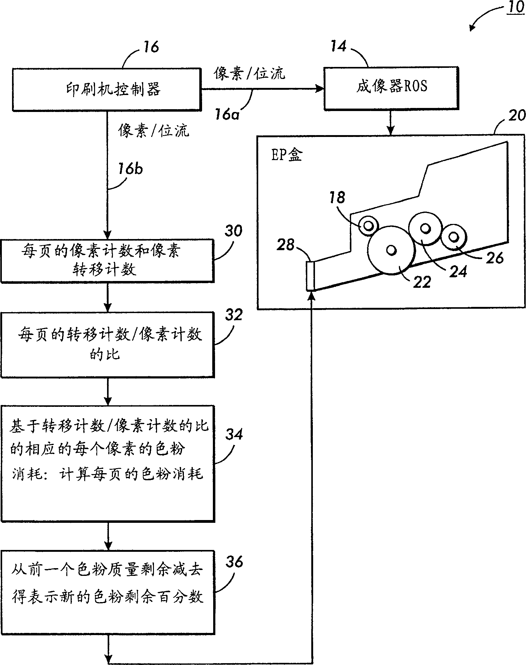
[0017] figure 1 is a schematic diagram and flowchart of an example printing press imaging material using a computing system. figure 1 The system shown and disclosed is a single element non-magnetic toner development system. Image developer material (e.g., toner) consumption monitoring sections may be provided for various xerographic electronic printing and / or digital copiers, utilizing various image generators, such as laser beams, LED arrays or bars, biased electrodes, Ion emitters, printheads, etc., electrically form an electrostatic latent image on an imaging member for imaging of a digital image input signal, thereby forming a latent image on the imaging member, which is then developed using known image developer materials. The imaging member may be a photoconductor drum or a belt. The developed image is then transferred to copy paper. Such systems can be used with color and / or black and white printers.

[0018] see figure 1 , which schematically shows an electronic p...


PUM


Abstract

The present invention discloses a method for estimating toner usage in a digital xerographic process. The method calculates a transfer count / pixel count ratio using the pixel transfer count and the pixel count for a printed image and provides an estimate of toner consumption based on the transfer count / pixel count ratio.

Description

technical field [0001] The present invention discloses a method of generating a toner gas metric by means of pixel counts and pixel transition counts using different types of images. Using the ratio of conversion counts to pixel counts yields more accurate estimates than simple pixel counts of toner consumption by image type. Different types of images consume different toner qualities for the same number of pixel counts due to scattered field development effects. By monitoring the switching count (laser on / laser off, or laser off / laser on), it is possible to determine what type of image is being exposed on the photoreceiving device and thus get a better estimate of toner usage. Background technique [0002] In a typical xerographic printing process, the photosensitive member is charged to a substantially uniform potential, rendering its surface photosensitive. The charged photosensitive member is selectively exposed to dissipate the charge in the illuminated area thereon. ...

Claims


Application Information

Patent Timeline
IPC IPC(8): G03G15/00G03G15/06G03G15/08G03G21/00H04N1/29
CPCG03G15/0824G03G15/0849G03G15/556G03G15/06
Inventor K·H·黄L·P·陈W·F·费尔布里奇P·G·哈亚迪纳塔
Owner XEROX CORP
Learn More