Glass cone for cathode-ray tube

A technology for cathode ray tubes, which is applied to the sealing end of the angular deflection coil part, can solve the problems of deterioration of appearance and appearance around the welded part, inconsistent shape, and inability to weld, etc., and achieves suppression of appearance and appearance. Welded state, effect of thinning

Inactive Publication Date: 2005-03-23
NIPPON ELECTRIC GLASS CO LTD
View PDF3 Cites 0 Cited by
  • Summary
  • Abstract
  • Description
  • Claims
  • Application Information

AI Technical Summary

Problems solved by technology

Therefore, the shapes of the opposite ends of the deflection yoke portion 5 and the neck tube 3 become inconsistent, and the welding of the two cannot be performed satisfactorily, and in the direction along the major axis LA, the ends of the deflection yoke portion 5 partially protrude, Prevents the periphery of the weld from forming a uniform shape over the entire circumference
As a result, not only the appearance and aesthetics of the periphery of the welded portion deteriorate, but also poor welding such as local thinning of the welded portion may occur in the direction along the major axis LA, which may cause strength problems around the welded portion.
[0011] Moreover, even if the neck tube 3 is elongated or oval, for example, if the amount of glass melting at the end of the deflection yoke portion 5 is too large, the cross-sectional shape of the end is more along the edge than the cross-sectional shape of the neck tube 3. A long oval or ellipse is formed in the direction of the major axis LA, and the shapes of the opposite ends of the two become inconsistent, so the same problem as above occurs

Method used


Image

  • Glass cone for cathode-ray tube
  • Glass cone for cathode-ray tube
  • Glass cone for cathode-ray tube

Examples


Embodiment Construction

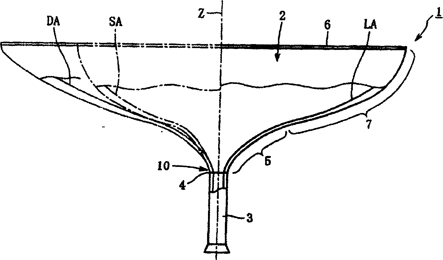
[0056] Embodiments of the present invention will be described below with reference to the attached drawings. In addition, the basic structure of the glass funnel for a cathode ray tube according to the embodiment of the present invention is different from that of the known Figure 6 The same as the existing example shown, so in the following description and each figure referred to in the description, the same as Figure 6 Components that are common to the shown conventional examples are denoted by the same symbols and their detailed descriptions are omitted.

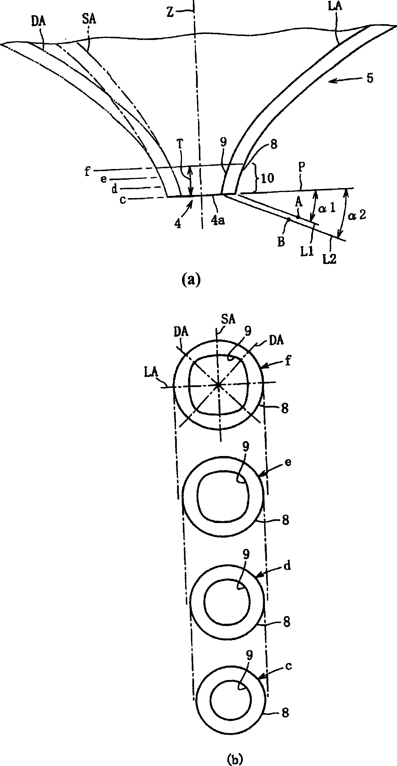
[0057] figure 1 Shown is a front view showing a main part of the glass funnel for a cathode ray tube according to the first embodiment of the present invention. In addition, in the same figure, the section indicated by symbol SA (the section indicated by the dotted line) shows the section including the minor axis SA and the pipe axis Z, and the section indicated by the symbol LA (the section indicated by the solid line)...


PUM


Abstract

The invention provides a glass cone for cathode-ray tube to avoid problems such as improper mismatch of cross section shape produced between both facing ends of the yoke and the neck tube of a glass funnel for a cathode-ray tube when they are welded, and worsening of the appearance of the periphery of the welded and sealed part, local defective welding and sealing, and the problem of welding and sealing strength. In an end region on a small-opening end 4 side of the square yoke portion 5 of the funnel 1, an extended portion 10 is provided whose external surface 8 and inner surface 9 dimensions in their radial directions gradually increase uniformly extending over the whole periphery, as they approach a large-opening end 6 side. The extended portion 10 is formed making the end face 4a of the small-opening end 4 starting end. The contour lines of the external surface 8 and the internal surface 9 of the extended portion 10 in its cross section containing a tube axis Z, are formed with individual arcs having the centers of curvature A, B respectively in regions which are to the peripheral sides of the surfaces and more to the neck tube 3 side than the end surface 4a of the opening end 4.

Description

technical field [0001] The present invention relates to a glass funnel for a cathode ray tube, and more particularly to an improved technique for sealing the end of a deflection deflection deflection deflection deflection angle where the neck tube is sealed in a cone including a main body and a sidewall portion of the deflection deflection deflection deflection angle. Background technique [0002] As is well known, the main components of a cathode ray tube include a glass panel for a cathode ray tube (hereinafter also simply referred to as a panel) having a substantially rectangular image display portion, and a cathode ray tube that seals the panel and allows electron beams to pass through the inside. A glass funnel (also referred to as a funnel hereinafter) is used for the tube. Such as Figure 6 As shown, the aforementioned cone 1 includes a main body portion 7 as a side wall portion 2, which includes a deflection coil portion 5 with a small open end 4 where the neck tube ...

Claims


Application Information

Patent Timeline
Patent Type & Authority Applications(China)
IPC IPC(8): H01J29/86
Inventor 八尾克美
Owner NIPPON ELECTRIC GLASS CO LTD
Why Eureka
Try Eureka