Cable terminating apparatus and method

A technology for cables and equipment, used in the field of termination equipment, to solve problems such as non-flush cutting, contact with shielding or conductive elements, etc.

Active Publication Date: 2005-03-23
TE CONNECTIVITY CORP
View PDF0 Cites 16 Cited by
  • Summary
  • Abstract
  • Description
  • Claims
  • Application Information

AI Technical Summary

Problems solved by technology

Cutting with prior art tools may not cut flush, exposing wire ends to possible contact with shielding or conductive elements

Method used


Image

  • Cable terminating apparatus and method
  • Cable terminating apparatus and method
  • Cable terminating apparatus and method

Examples


Embodiment Construction

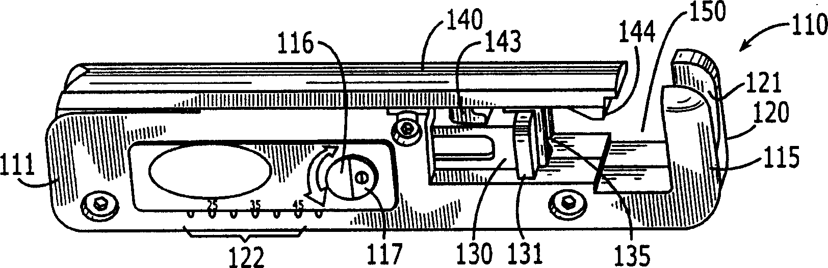
[0024] figure 1 A preferred embodiment of the invention is shown. An example extrusion tool is shown generally at 110 . Body 111 is shown, which includes housings 115 and 120 . The shown wire stripping groove 116 is integral with the body 111 and contains a wire stripping knife 117, which will be further described below. A measuring scale 122 is also shown, used inter alia to measure the stripped length of the cable. Also visible is the action element 130 with a linked finger puller 131 and pusher 135 .

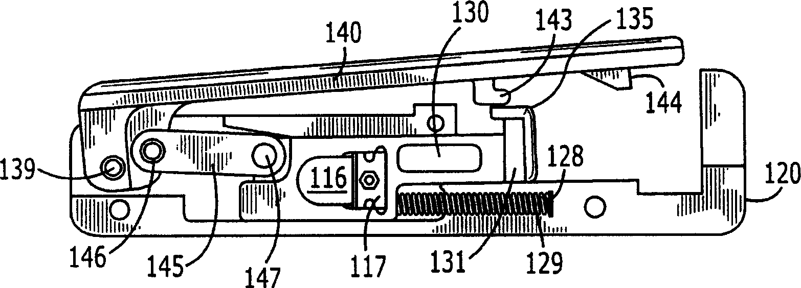
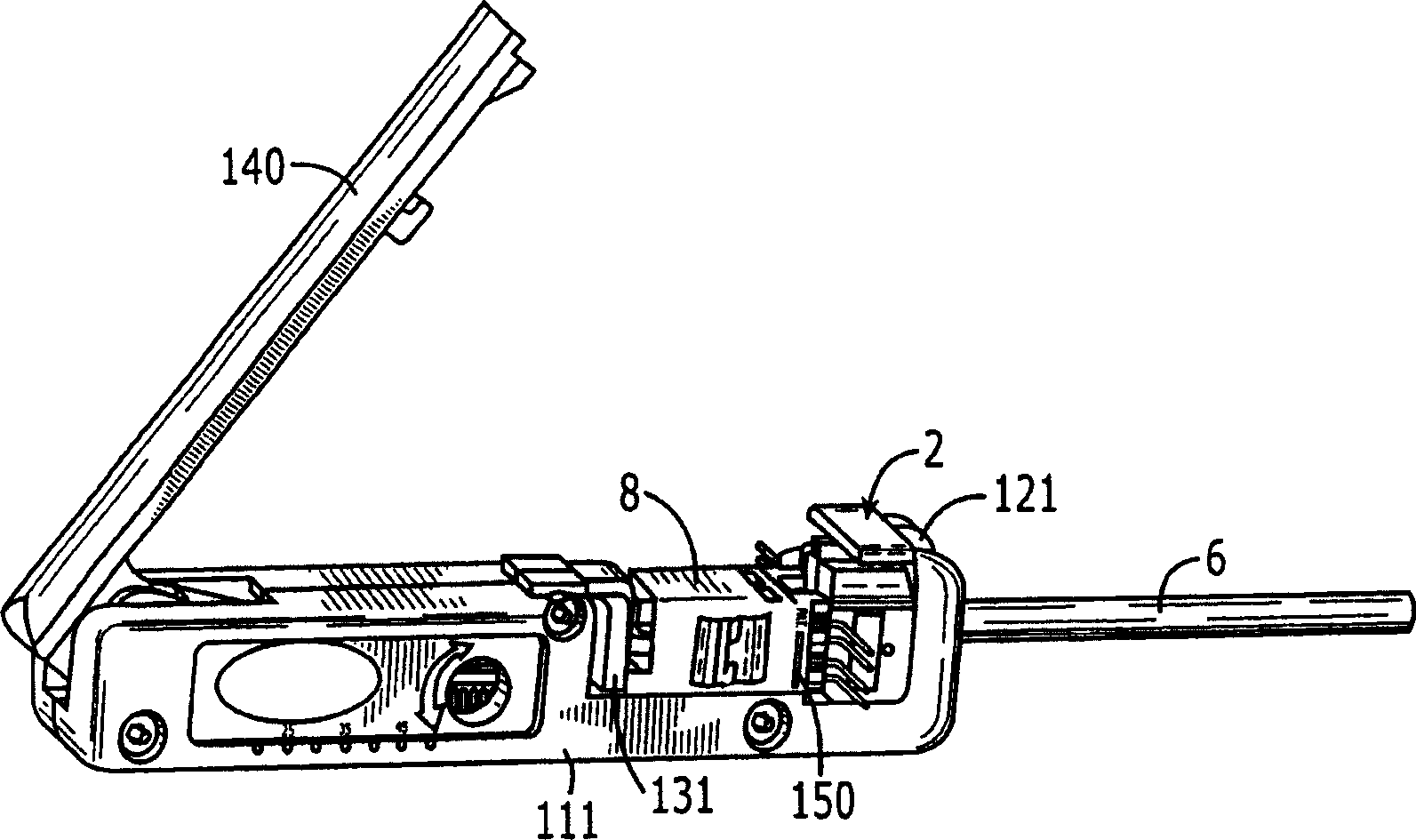
[0025] The handle 140 is shown in the closed position. If desired, the handle 140 can also be placed in a locked position wherein the lug 143 of the handle 140 and the action member 130 are engaged in a mating relationship. Lugs 144 provide base engagement for a cable manager, which will be described further below. The cable channel 121 provides passage for cables, and for mating engagement of cable grippers on the cable manager, described further below.

[0026] fig...


PUM


Abstract

Apparatus and methods are shown for holding a plurality of wires of a cable in fixed positions relative to each other for assisting in the termination of the cable with a connector having plurality of contacts possibly of the insulation displacement type. The device to connect a cable to a connector is provided with a support means having an arrangement means to arrange electric wires of the cable in an alienated relationship in which the electric wires are fixed to one another, a guiding means which guides a terminal of the connector into an electrically contacted state with the electric wires by being engaged with a complementary surface of the connector at engagement with the device, and a squeezing tool having a means to energize the connector in a state that engagement to the support means is completed. As for the squeezing tool, squeezing force in an orthogonal direction to the axis of the cable is used so as to energize the cable in the state that engagement of the connector with the support means is completed.

Description

technical field [0001] The present invention relates to a termination device for connecting a connector at the end of a cable and a method for effecting the termination. Background technique [0002] With cables containing multiple conductors and connectors containing multiple terminals, it can be difficult to terminate insulated connection (IDC) cables, especially if the cables contain many small diameter conductors such as are typically used in communications equipment. [0003] The tools used in the prior art for such terminations are impact tools, which require pushing and inserting the wires into the terminals of the connector one at a time, or terminating multiple wires at the same time. Termination of wires one at a time is a time consuming operation, and termination of multiple wires can result in operational difficulties due to the stress exerted on the wires. Additionally, because the connectors are often disconnected, field removal operations are often required, ...

Claims


Application Information

Patent Timeline
Patent Type & Authority Applications(China)
IPC IPC(8): H01R43/01
CPCY10T29/53213Y10T29/53209Y10T29/5313Y10T29/53283Y10T29/53217Y10T29/5151Y10T29/53222Y10T29/514Y10T29/53243Y10T29/53257H01R43/015
Inventor 克里斯托弗·J·卡拉希
Owner TE CONNECTIVITY CORP
Why Eureka
Try Eureka