Pump with function of measuring fixed amount
A functional and certain amount of technology, applied in the direction of pumps, piston pumps, single handheld devices, etc., can solve the problems of polluting the surroundings, inadvertently pressing the hand pressure part, waste of discharge, etc.
- Summary
- Abstract
- Description
- Claims
- Application Information
AI Technical Summary
Problems solved by technology
Method used
Image
Examples
Embodiment 1
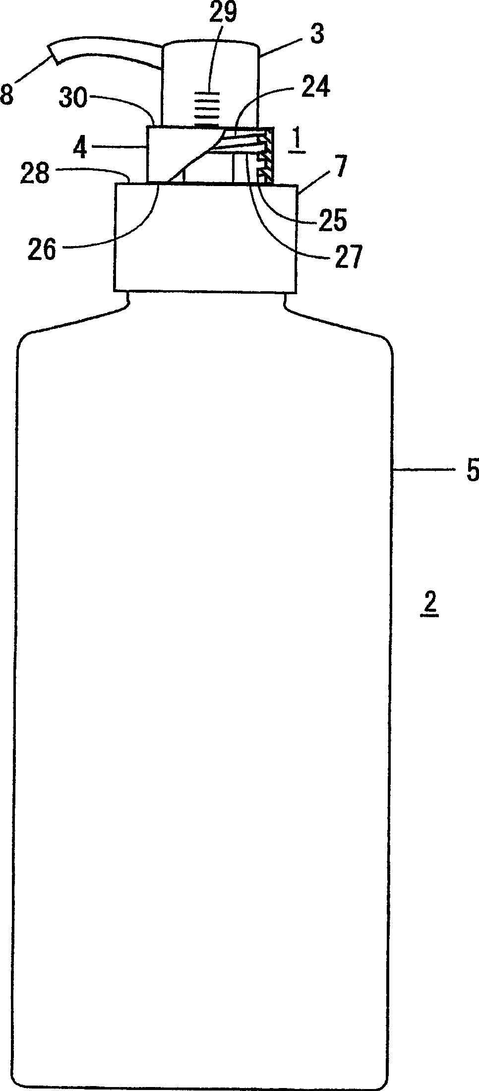
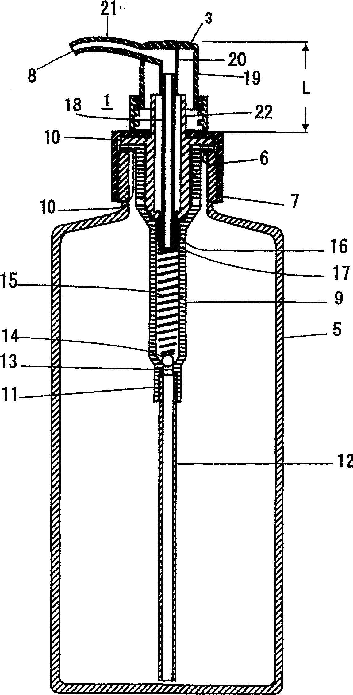
[0111] figure 1 and figure 2 Example 1 is a representation of the pump. figure 1 is a front view of a liquid container 2 with a pump 1 . The stopper 4 which limits the amount of depression of the head 3 of the pump is shown in partial section. figure 2 It is a central longitudinal section view.
[0112] as figure 1 and figure 2 As shown, the pump 1 in which the liquid container 2 is integrated with the cap part 7 at the upper opening 6 of the bottle-shaped container body 5 is provided as a cap. The container body 5 is widely used as a soft resin material such as polypropylene, but the material is not limited, and it can also be made of hard resin, glass and other materials, and the general circulation container can be selected appropriately.
[0113] This pump 1 is a pump of very general construction related to the discharge function itself of the container contents of a push-down type liquid pump, which is made as part of the cover of the liquid container 2, and b...
Embodiment 2
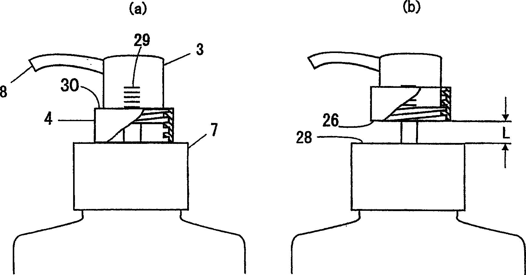
[0126] Figure 5 to Figure 9 Example 2 representing the pump, Figure 5 It is a front view of important parts when the stopper 4 is set at the maximum discharge position, Figure 6 (a) is a partial longitudinal sectional view of the head 3 of the pump at this time and Figure 6(b) A partial longitudinal sectional view of the pump head 3 when the stopper 4 is installed at the pump head fixing position.
[0127] Such as Figure 5 and Figure 6 As shown, in this embodiment, the stopper 4 is installed in the head 3 of the pump. The head 3 of the pump forms an internal thread 25 on the lower inner periphery of the outer cylinder 19 . The connecting pipe 18 is inserted into the inner cylinder 20 . And, a stopper 4 having an external thread 24 threadedly engaged with the internal thread 25 is accommodated in the head 3 of the pump. The stopper 4 is provided with a flange portion 10 at the lower end of a cylindrical body having an external thread 24 on the outer periphery there...
Embodiment 3
[0132] Figure 10 Example 3 of the pump of the present invention is shown, (a) is the fixed position of the head of the pump, and (b) is the state where the stopper 4 is installed at the maximum discharge position.
[0133] In this embodiment, a stopper 4 is used in which an external thread 24 is formed on the outer periphery of the connecting pipe 18 , an internal thread 25 is threadedly engaged with the external thread 24 of the connecting pipe 18 , and a stopper 4 is used. exist Figure 10 Among them, the cylindrical portion 31 covering the cap member 7 is provided on the outer edge of the planar portion 32 , and the scale 29 is provided on the cap member 7 . The flat portion 32 of the stopper 4 is positioned in a range between the lower end 27 of the pump head 3 and the upper face 28 of the cap member 7 to set the pressing amount L steplessly.
[0134] In addition, in this embodiment, in order to prevent the pump head 3 and the connecting pipe 18 from rotating relative t...
PUM
 Abstract
Description
Claims
Application Information
 - R&D
- Intellectual Property
- Life Sciences
- Materials
- Tech Scout
- Unparalleled Data Quality
- Higher Quality Content
- 60% Fewer Hallucinations
Browse by: Latest US Patents, China's latest patents, Technical Efficacy Thesaurus, Application Domain, Technology Topic, Popular Technical Reports.
© 2025 PatSnap. All rights reserved.Legal|Privacy policy|Modern Slavery Act Transparency Statement|Sitemap|About US| Contact US: help@patsnap.com


