
Optical fiber connector disassembling tool

A technology for optical fiber connectors and disassembly tools, which is applied in the direction of optical fiber/cable installation, optics, light guides, etc., and can solve the problems that no one has raised about optical fiber connectors

Inactive Publication Date: 2005-04-06
JAPAN AVIATION ELECTRONICS IND LTD +1
View PDF1 Cites 0 Cited by
  • Summary
  • Abstract
  • Description
  • Claims
  • Application Information

AI Technical Summary

Problems solved by technology

However, no one has yet proposed any removal tool for a fiber optic connector comprising an outer part into which and from a ferrule to be inserted and ejected

Method used


Image

  • Optical fiber connector disassembling tool
  • Optical fiber connector disassembling tool
  • Optical fiber connector disassembling tool

Examples


Embodiment Construction

[0038] Refer to the following Figure 6-16 A fiber optic connector removal tool according to one embodiment of the present invention is described.

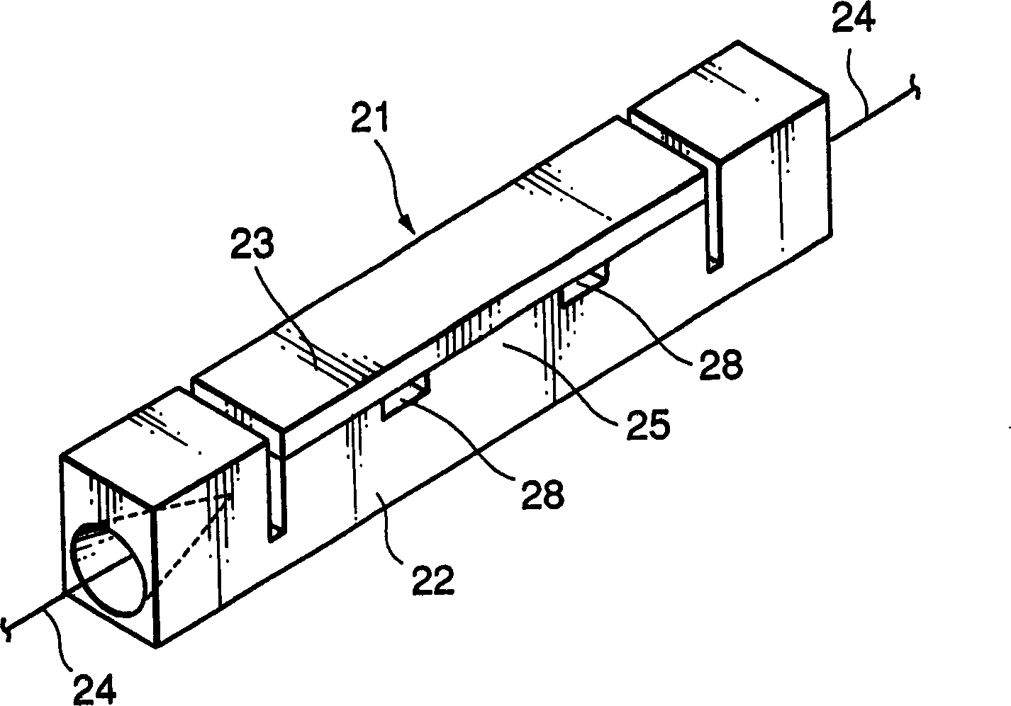
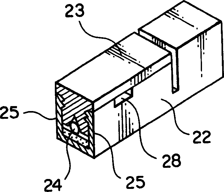
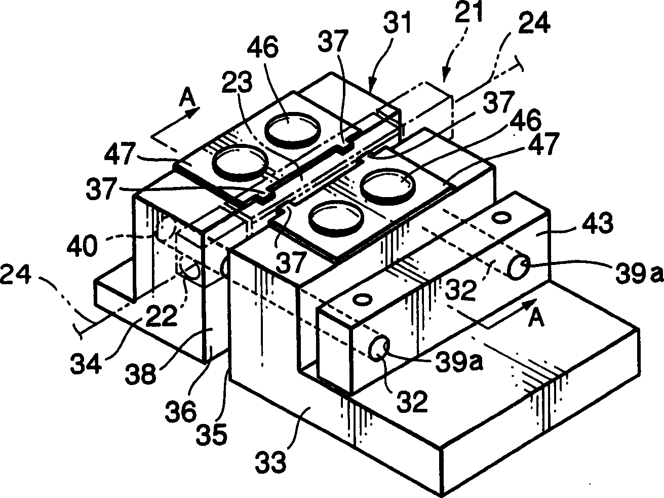
[0039] Figure 6 The perspective view of FIG. 2 shows a removal tool 1 and a plug connector (ie, an optical fiber connector) 11 to be removed by the removal tool 1 .

[0040] The removal tool 1 includes a rectangular plate-shaped body part 2, a holding block 3 fixed to the body part 2, a rail 2a provided on the surface of the body part 2, a slider 4 slidably movable on the rail 2a, and a block for sliding the slider. 4 of the operation part 5.

[0041] A pair of rectangular plates 3a, 3a are respectively fixed to the upper surface of the holding block 3 with two pairs of screws 3b, 3b. The intermediate space between the pair of plates 3 a , 3 a is a housing part 3 c for accommodating the plug connector 11 . A curved guide plate 3 d for guiding a cord connected to the plug connector 11 is fixed at the center of one side of the ...


PUM


Abstract

A disassembling tool includes a holding block having a housing portion for accommodating a plug connector, a slide block, and a handling part for sliding the slide block. The plug connector comprises an outer member and a plug frame and is accommodated in the housing portion of the holding block. When turning a handle of the handling part, the slide block is slidably move d so that projections provided on the slide block release the locking between locking portions of the outer member and locked portions of the plug frame. Followin g this, contact portions provided on the slide block come into contact with th e plug frame so as to push it out of the outer member by a given amount.

Description

technical field [0001] The present invention relates to a tool for removing optical fiber connectors. Background technique [0002] refer to Figure 1-5 , an optical fiber connector and an optical fiber connector removal tool for removing the optical fiber connector will be described. An optical fiber connector removal tool of this type is disclosed, for example, in Japanese Patent Application Laid-Open (JP-A) No. 9-96734. [0003] figure 1 and figure 2 A fiber optic connector 21 is shown. The optical fiber connector 21 includes an elongated rod-shaped base 22 and a gland 23 attached to the upper side of the base 22 . Between the base 22 and the gland 23 is held a pair of optical fibers 24, each end of which are abutted to each other for connection. The base 22 has a pair of walls 25 along the lengthwise direction. The gland 23 is fitted between a pair of walls 25 . Thus, a pair of optical fibers 24 is held between the base 22 and the gland 23 . Two insertion holes...

Claims


Application Information

Patent Timeline
Patent Type & Authority Applications(China)
IPC IPC(8): G02B6/36G02B6/00G02B6/24G02B6/38G02B6/46
CPCG02B6/3898G02B6/3807
Inventor 是枝雄一三宫真牟田口清之阿部宜辉小林胜长濑亮
Owner JAPAN AVIATION ELECTRONICS IND LTD
Features
  • Generate Ideas
  • Intellectual Property
  • Life Sciences
  • Materials
  • Tech Scout
  • Unparalleled Data Quality
  • Higher Quality Content
  • 60% Fewer Hallucinations
Learn More