
Fiber optic splice storage apparatus and methods for using the same

a fiber optic splice and storage apparatus technology, applied in the field of optical fiber products, can solve the problems of limiting the ability to provide a suitable, unmanageable rat's nest of tangled fibers, etc., and achieve the effect of limiting the bending of optical fibers

Inactive Publication Date: 2008-03-04
COMMSCOPE TECH LLC
View PDF14 Cites 109 Cited by
  • Summary
  • Abstract
  • Description
  • Claims
  • Application Information

AI Technical Summary

Benefits of technology

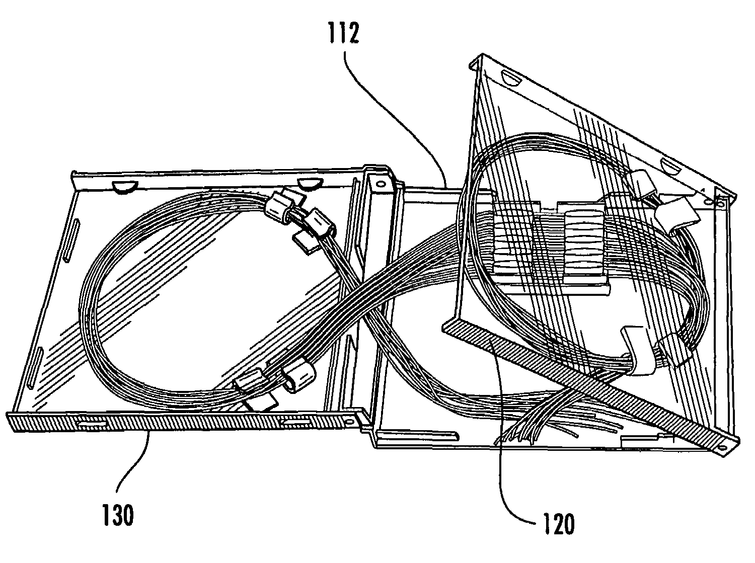
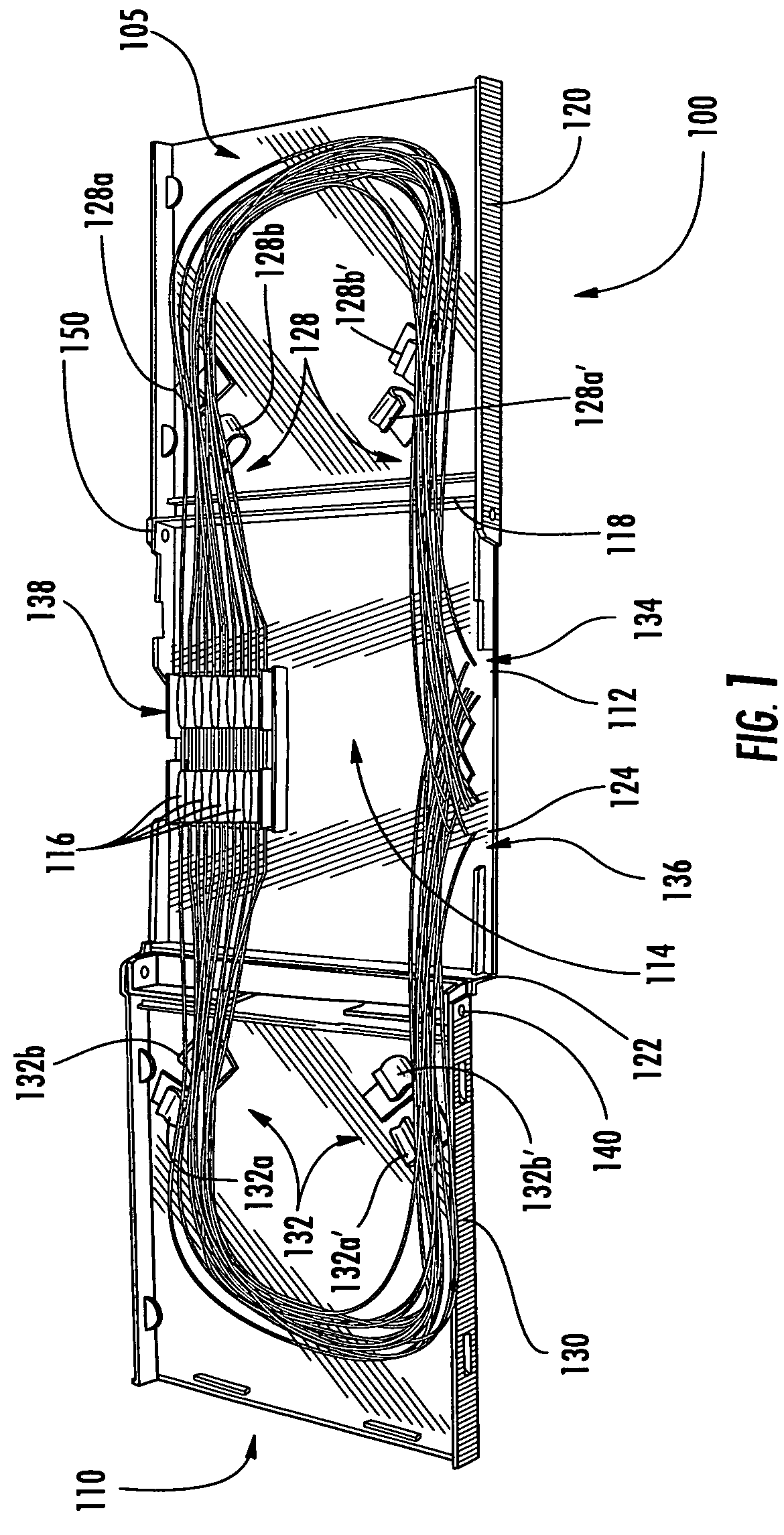
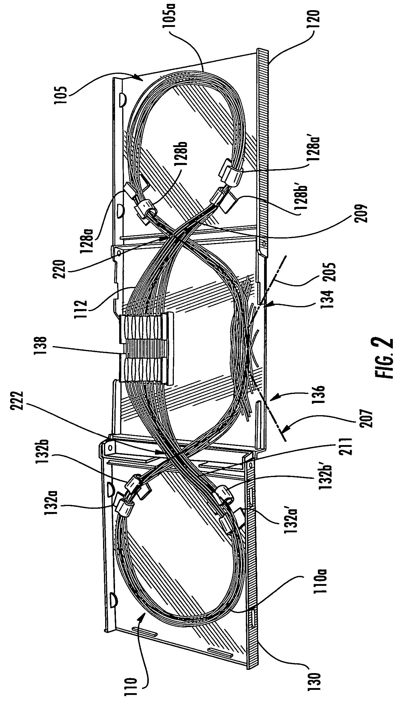
[0012]In other embodiments of the present invention, a tri-fold fiber splice tray includes a central segment and first and second slack fiber storage segments. The central segment defines a splice chamber configured to receive a plurality of fiber optic splices. The first slack fiber storage segment is pivotally connected to a first end of the central segment and has an open position extending from the first end away from the central segment and a closed position extending over the central segment. The second slack fiber storage segment is pivotally connected to a second end of the central segment, opposite the first end. The second slack fiber storage segment has an open position extending from the second end away from the central segment and a closed position extending over the central segment. Tray mounting legs extend from a third end of the central segment, the third end extending from the first end to the second end. The tray mounting legs are configured to allow the splice tray to be pivotally mounted to an enclosure. A fiber entrance to the splice chamber is on the third end of the central segment between the tray mounting legs and the second end. A fiber exit to the splice chamber is on the third end of the central segment between the tray mounting legs and the first end. A first and second slack fiber guide member on the first slack fiber storage segment are configured to receive and retain a loop of optical fibers. The fiber entrance and the first slack fiber guide member define a first fiber path extending from the central segment to the first slack fiber storage segment. A third and fourth slack fiber guide member on the second slack fiber storage segment are configured to receive and retain a loop of optical fibers. The fiber exit and the third slack fiber guide member define a second fiber path extending from the central segment to the second slack fiber storage segment. A splice receiving member is provided on the central segment. The splice receiving member and the second slack fiber guide member define a third fiber path extending from the central segment to the first slack fiber storage segment. The splice receiving member and the fourth slack fiber guide member define a fourth fiber path extending from the central segment to the second slack fiber storage segment. An intersection of the first and third fiber paths define a first fiber cross-over location proximate an intermediate portion of the first end to limit bending of optical fibers extending along the first and third fiber paths when the first slack fiber storage segment is moved from its opened position to its closed position. The second and fourth fiber paths define a second fiber cross-over location proximate an intermediate portion of the second end to limit bending of optical fibers extending along the second and fourth fiber paths when the second slack fiber storage segment is moved from its opened position to its closed position.

Problems solved by technology

However, various applications may have limited space available for receiving such splice trays, which may constrain the ability to provide a suitable splice tray.
Furthermore, conventional splice trays are typically flat and nonmoving, thus, generally requiring the splice technician to manually load and extract the fibers from the tray.
If all the fibers are not completely unbundled each time a splice is made, an unmanageable rat's nest of tangled fibers may result from repeated access for adding fiber splices.

Method used


Image

  • Fiber optic splice storage apparatus and methods for using the same
  • Fiber optic splice storage apparatus and methods for using the same
  • Fiber optic splice storage apparatus and methods for using the same

Examples


Embodiment Construction

[0029]The present invention now will be described more fully hereinafter with reference to the accompanying drawings, in which illustrative embodiments of the invention are shown. In the drawings, the relative sizes of regions or features may be exaggerated for clarity. This invention may, however, be embodied in many different forms and should not be construed as limited to the embodiments set forth herein; rather, these embodiments are provided so that this disclosure will be thorough and complete, and will fully convey the scope of the invention to those skilled in the art.

[0030]It will be understood that, although the terms first, second, etc. may be used herein to describe various elements, components, regions, layers and / or sections, these elements, components, regions, layers and / or sections should not be limited by these terms. These terms are only used to distinguish one element, component, region, layer or section from another region, layer or section. Thus, a first elemen...


PUM


Abstract

A fiber optic splice storage apparatus includes a central segment defining a splice chamber configured to receive a plurality of fiber optic splices, a first slack fiber storage segment pivotally connected to a first end of the central segment and having an open position extending from the first end away from the central segment and a closed position extending over the central segment, and a second slack fiber storage segment pivotally connected to a second end of the central segment, opposite the first end, the second slack fiber storage segment having an open position extending from the second end away from the central segment and a closed position extending over the central segment. A first plurality of slack fiber guide members on the first slack fiber storage segment are configured to receive and retain a loop of optical fibers and a second plurality of slack fiber guide members on the second slack fiber storage segment are configured to receive and retain a loop of optical fibers.

Description

RELATED APPLICATIONS[0001]The present application claims priority from U.S. Provisional Application No. 60 / 729,575, filed Oct. 24, 2005, the disclosure of which is hereby incorporated herein in its entirety by reference.BACKGROUND OF THE INVENTION[0002]The present invention relates to optical fiber products and, more particularly, to optical fiber storage products and methods for using the same.[0003]Optical fiber networks are increasingly being installed to support high-speed voice and data communications. Increasingly, the optical fiber coupling is being expanded out from the central office of the communication service provider companies, such as Regional Bell Operating Companies (RBOCs) to the subscriber locations, such as homes or businesses, where conventional copper wiring was conventionally used.[0004]In various locations in a fiber optic network, fibers must be spliced or the like in an organized fashion. Fiber splice trays or the like may be used to provide such splices in ...

Claims


Application Information

Patent Timeline
Patent Type & Authority Patents(United States)
IPC IPC(8): G02B6/00
CPCG02B6/4454G02B6/4455
Inventor ALLEN, BARRY W.
Owner COMMSCOPE TECH LLC
Learn More