Hollow universal joint

a universal joint and universal technology, applied in the direction of yielding couplings, mechanical devices, couplings, etc., can solve the problems of buckling of the joint in straight sections of pipelines, inability to protect cabling, and introducing errors

Active Publication Date: 2008-04-08
PII CANADA
View PDF11 Cites 10 Cited by
  • Summary
  • Abstract
  • Description
  • Claims
  • Application Information

AI Technical Summary

Benefits of technology

[0015]In one embodiment, the first and third members have hollow portions respectively adjacent the first and second yoke rings and the universal joint further comprises a stiffening member extending from the hollow portion of the first member to the hollow portion of the third member through the first hollow yolk ring, the second member and the third yolk ring. The stiffening member is snugly fit into the hollow portion of the first member, the hollow portion of the third member and the second member. This stiffening member acts to limit bending of the joint about a central axis running through the joint. This is particularly advantageous when such a joint is used between two magnetizing sections of a pig train because the stiffening member maintains the straight when the pig is travelling along straight lengths of pipeline. In an alternative embodiment, it is envisaged that the stiffening member surrounds at least the first and second hollow yolk rings and the second member to limit axial bending freeplay of the joint.

Problems solved by technology

However, this type of universal joint does not protect any cabling that extends between sections of the pig train.
This cabling may wear when rubbing against the inside walls of the pipeline particularly when the pig train is negotiating a sharp bend in the pipe line.
Also, the joint, particularly when configured as a double universal joint, has a tendency to buckle causing potential collision of adjacent sections of the pig train.
While the joint is designed to negotiate bends in the pipeline any buckling of the joint in straight sections of a pipeline introduces error into the magnetically sensed readings of two magnetizer sections coupled by the joint.

Method used


Image

  • Hollow universal joint
  • Hollow universal joint
  • Hollow universal joint

Examples


Embodiment Construction

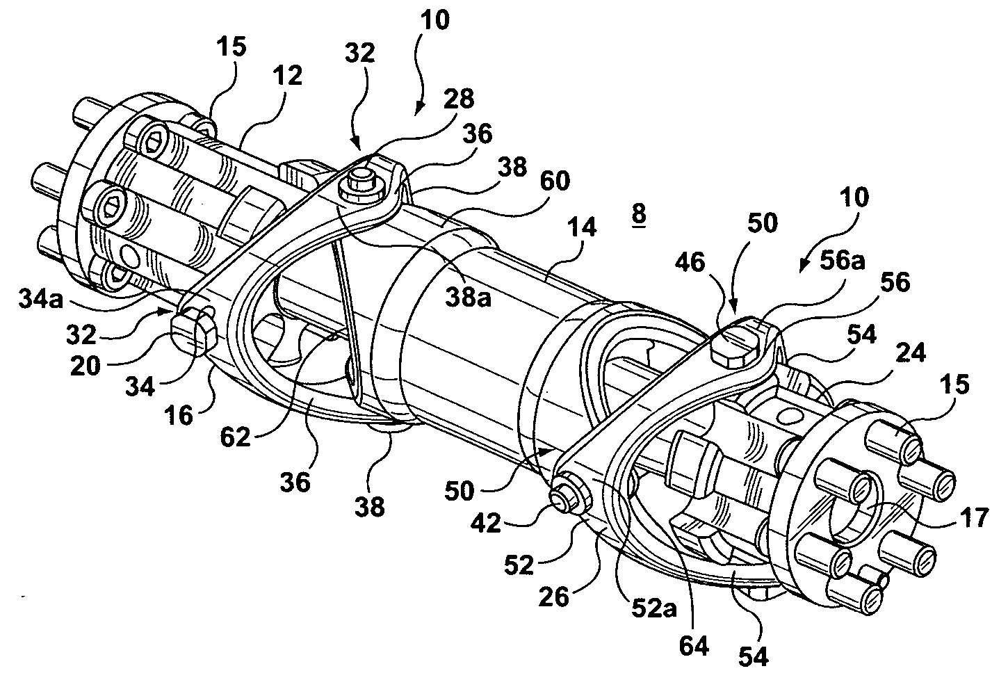
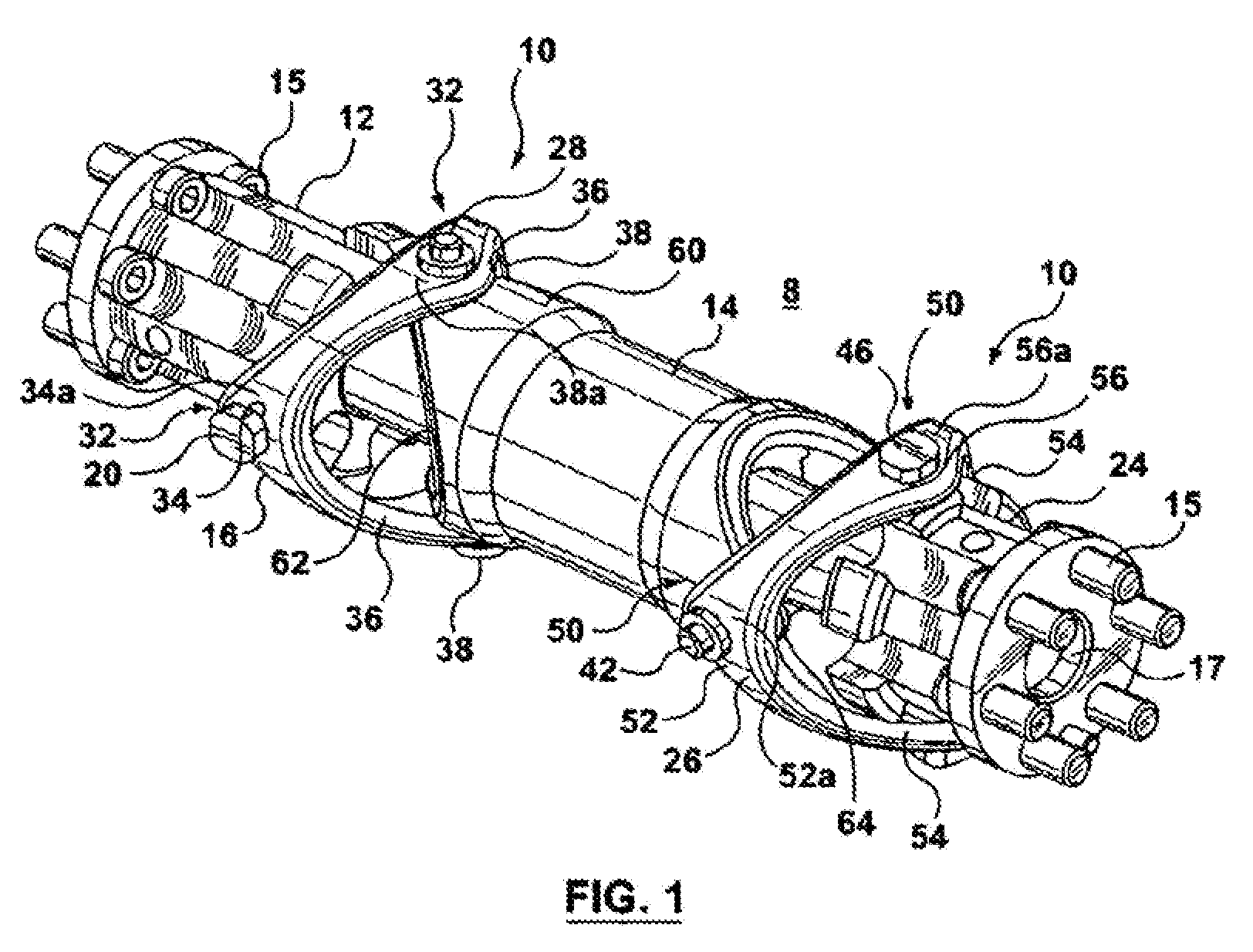
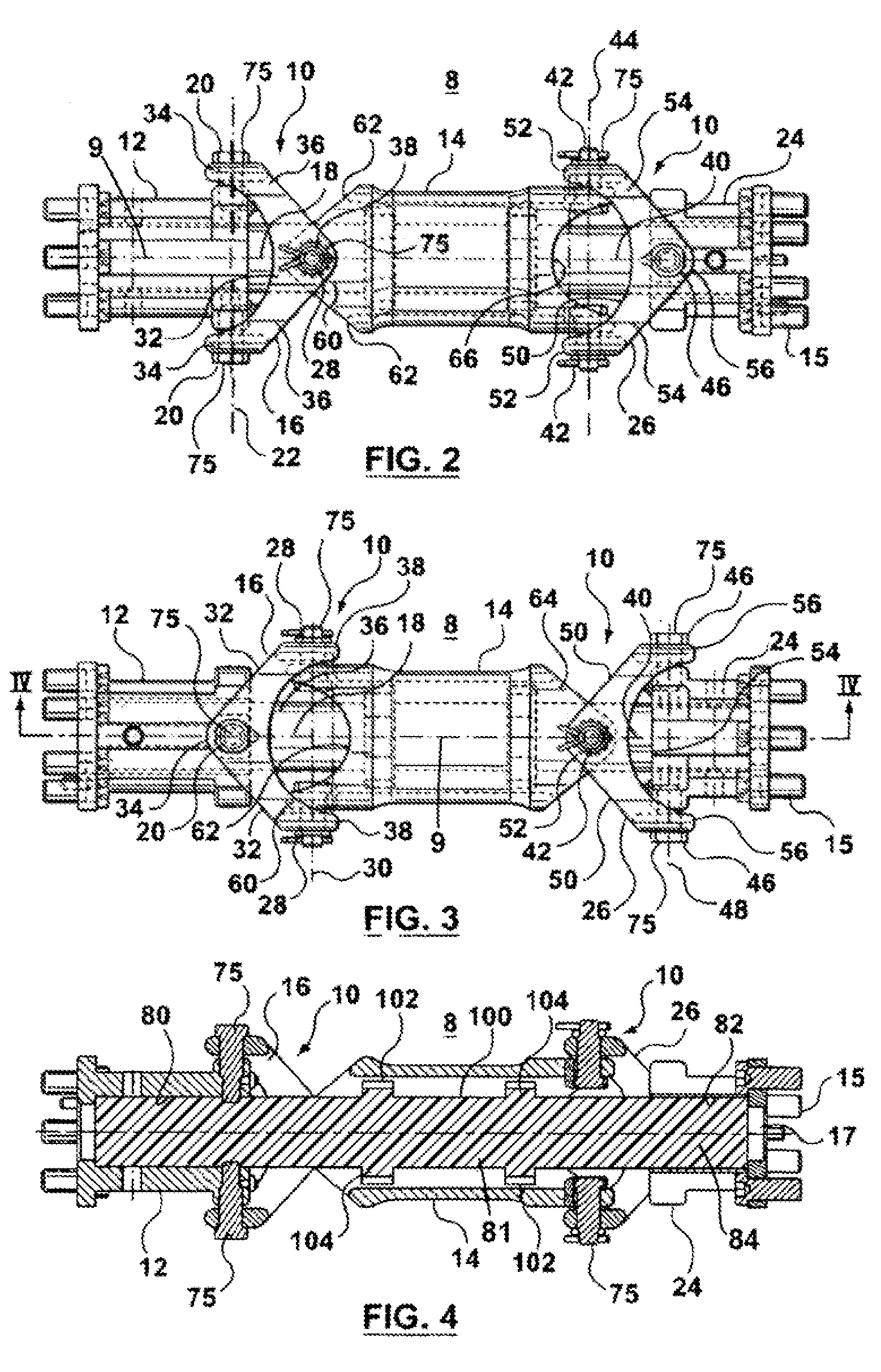
[0026]The present invention relates to a hollow universal joint and in particular to a double hollow universal joint adapted to protectively house cabling extending through the joint and / or utilizing a stiffening material limiting buckling of the joint.

[0027]Referring to FIGS. 1 through 4 there is shown a double hollow universal joint 8 having two hollow universal joints 10. The double universal joints 10 interconnect a first member 12, a second member 14 and a third member 24. It should be understood that the double hollow universal joint 8 shown in these Figures has specific application with respect to use in a pig train for pipeline inspection devices. Accordingly, the first member 12 and the third member 24 are shown as blocks having fastening bolts 15 and a hollow central bore 17 that is adapted to be attached to a pig device of a pig train. While the illustrations relate to this application, it should be understood that the first member 12 and the third member 24 may comprise ...


PUM


Abstract

A hollow universal joint having a first member, a second member and a first hollow yoke ring coupling the first member to the second member to transfer rotational motion between the first and second members. The first hollow yoke ring has a first central axis. The first hollow yoke ring has first pivot points pivotally coupled with the first member. The first pivot points define a first axis extending therebetween. The first pivot points are spaced from the first central axis. The first hollow yoke ring comprises second pivot points pivotally coupled with the second member. The second pivot points define a second axis extending therebetween. The second pivot points are spaced from the first central axis. The first axis extends orthogonal to the second axis and the first and second axes each extend orthogonal to the first central axis.

Description

BACKGROUND OF THE INVENTION[0001]The present invention relates to a hollow universal joint and in particular to a double hollow universal joint adapted to protectively house cabling extending through the joint and / or utilizing a stiffening material limiting buckling of the joint.[0002]Universal joints have been used to interconnect working sections of a pig train used to inspect pipelines. In particular, the universal joints may be used in a pig train to interconnect the tow section to a magnetizing section, between magnetizing sections and to connect the magnetizing section with downstream recording and control devices. The universal joints used in this application typically comprise two coupled shafts that extend along the axis of the pipeline when the pig is moving along a straight path in the pipeline.[0003]The universal joint is useful in allowing sections of the pig train to negotiate around bends in the pipe. However, this type of universal joint does not protect any cabling ...

Claims


Application Information

Patent Timeline
Patent Type & Authority Patents(United States)
IPC IPC(8): F16D3/42
CPCF16D3/32F16D3/42
Inventor KAPUSTIN, EUGENEFILIPPOVITCH, SERGEI
Owner PII CANADA
Why Eureka
Try Eureka