Lever type connector

a technology of lever type and connector, which is applied in the direction of coupling device connection, coupling parts engagement/disengagement, incorrect coupling prevention, etc., can solve the problems of difficult to easily fit the lever with the target connector, the temporary locking arm may deviate from the temporary locking protrusion, etc., to achieve the effect of improving reliability, reducing the outward bending of the temporary locking arm, and improving reliability

Active Publication Date: 2009-12-08
YAZAKI CORP
View PDF22 Cites 8 Cited by
  • Summary
  • Abstract
  • Description
  • Claims
  • Application Information

AI Technical Summary

Benefits of technology

[0010]The invention has been made to solve the aforementioned problem, and is to provide a lever type connector with high reliability by preventing an unnecessary deviation accident in the temporary locking of the lever.
[0013]According to a third aspect of the invention, in the lever type connector according to the second aspect, a clearance groove for avoiding interference of the lever side plate and the temporary locking protrusion at the time of swinging the lever is formed in the inner face of the lever side plate, and the bending restricting protrusion of the temporary locking arm is configured to go into the clearance groove.
[0014]According to the first aspect of the invention, even when the temporary locking arm is deformed by applying excessive external force to the lever in the state where the lever before connector fitting is at the temporary locking position, the bending restrict unit provided on the temporary locking arm restricts bending of the temporary locking arm in the temporary locking direction. Accordingly, the engagement state of the temporary locking arm and the temporary locking protrusion is kept, and thus the temporary locking arm does not easily deviate. Therefore, it is possible to keep the temporary locking state of the lever, and thus it is possible to improve reliability.
[0015]According to the second aspect of the invention, when the temporary locking arm is deformed, the outward bending of the temporary locking arm is restricted by engaging the protrusion provided on the temporary locking arm with the inner face side of the adjacent lever side plate. Therefore, it is possible to improve reliability just by providing the temporary locking with the protrusion.
[0016]According to the third aspect of the invention, as a void to which the protrusion goes at the time of deforming the temporary locking arm, the clearance grove provided on the inner face of the lever side plate to avoid the temporary locking protrusion is used. Therefore, it is unnecessary to secure a new void separately, and it is possible to improve reliability just by adding the protrusion.

Problems solved by technology

Accordingly, when excessive external force is applied to the temporary locking arm, the temporary locking arm may deviate from a temporary locking protrusion.
That is, when strong external force is applied to a lever at the time of keeping or transporting a connector in a temporary locking state, the temporary locking arm is bent in a deviation direction (outward direction) of the temporary locking arm by the force applied to the temporary locking arm, and thus the temporary locking may deviate.
When the temporary locking deviates, the position of the lever is not determined and it is difficult to easily fit the lever with a target connector.

Method used


Image

  • Lever type connector
  • Lever type connector
  • Lever type connector

Examples


Embodiment Construction

[0031]Hereinafter, an embodiment of the invention will be described with reference to the drawings.

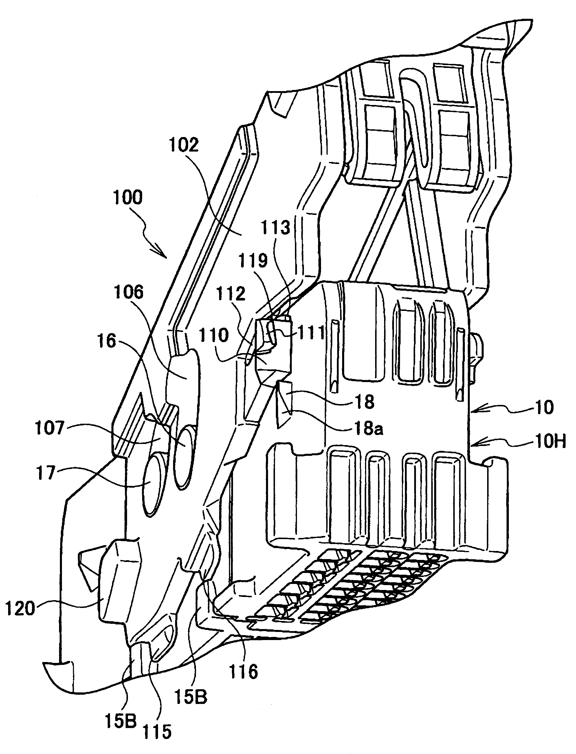
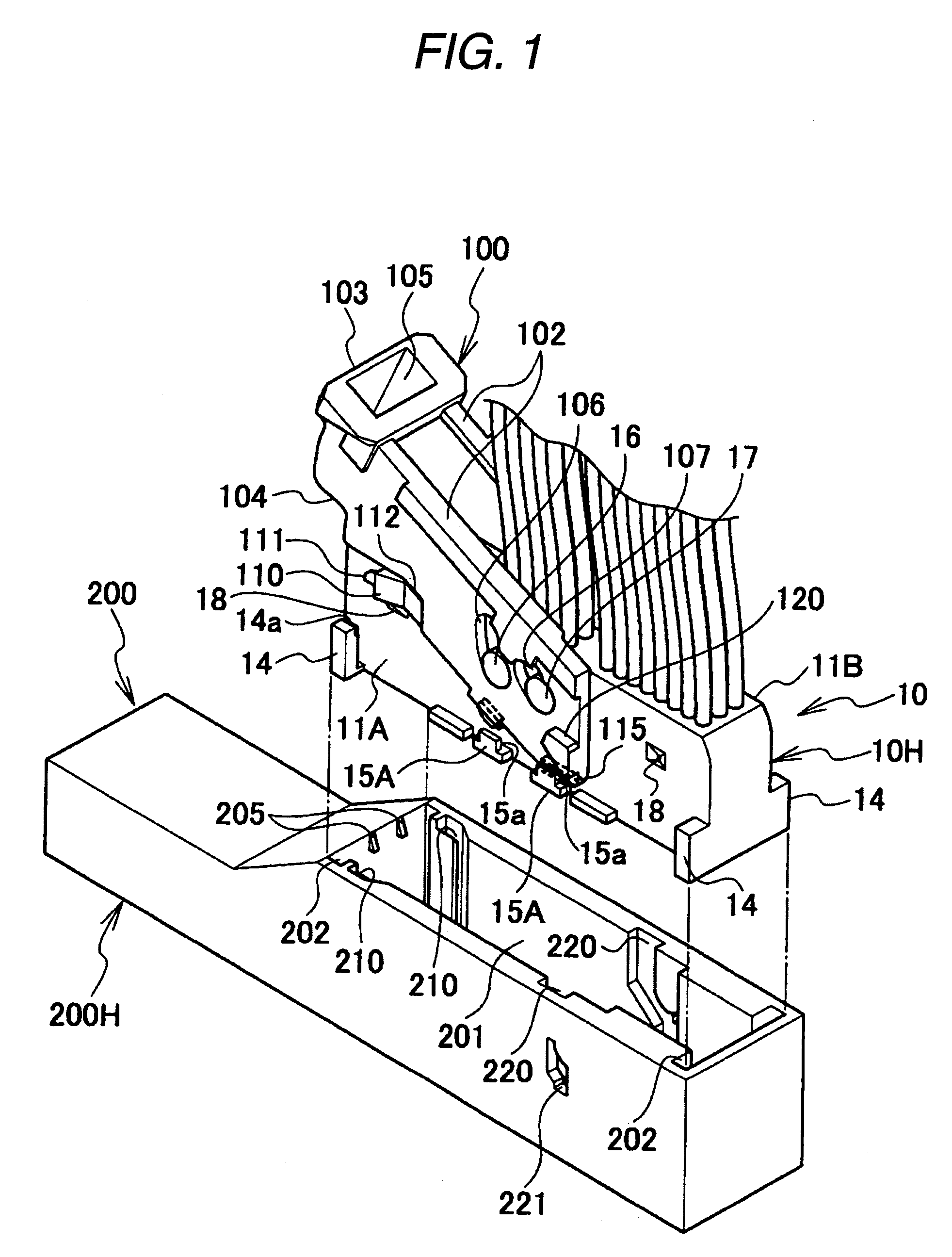
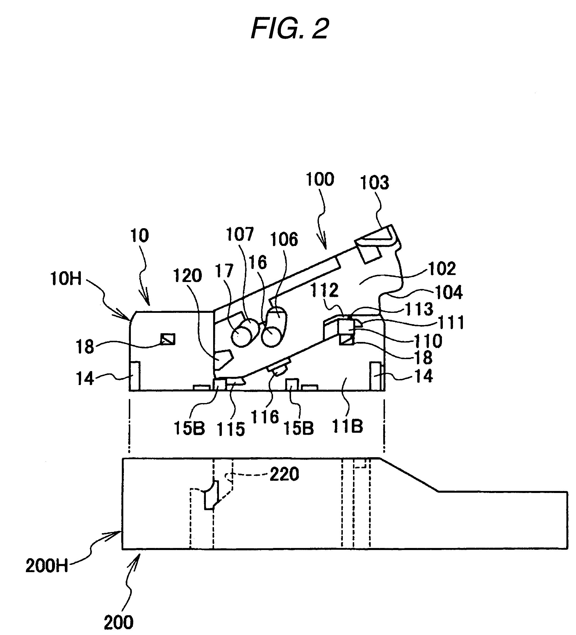
[0032]FIG. 1 is a perspective view illustrating a state before fitting of a lever type connector according to an embodiment. FIG. 2 is a side view as viewed from the side opposite to FIG. 1. FIG. 3 is a side view illustrating a state where a lever is mounted on a male connector and is kept at a temporary locking position. FIG. 4 is an enlarged view illustrating a main part. FIG. 5 is a perspective view as viewed from the bottom of a lever. FIG. 6 is a perspective view illustrating a temporary locking arm as viewed from the bottom. FIG. 7 is an enlarged perspective view illustrating relationship between a clearance groove and a protrusion provided on a temporary locking arm. FIG. 8 is a side view illustrating the state shown in FIG. 3 as viewed from the opposite side. FIG. 9 is an enlarged side view illustrating a state where external force is applied to the lever to deform the temporar...


PUM


Abstract

Provided is a lever type connector for fitting connectors by swinging a lever 110, in which a lever side plate 102 is provided with a temporary locking arm 110. The temporary locking arm is provided with a bending restricting protrusion 113. When the temporary locking arm is deformed by applying excessive external force to a lever in a state where the lever before connector fitting is positioned at a temporary locking position, the bending restricting protrusion 113 restricts bending of the temporary locking arm in a temporary releasing direction (outward direction) by engaging with the inner face side of the lever side plate.

Description

BACKGROUND OF THE INVENTION[0001]1. Field of the Invention[0002]The invention relates to a lever type connector capable of fitting or separating female and male connector housings with little force by a swing operation of a lever.[0003]2. Description of the Related Art[0004]A lever type connector is provided with a lever that is swingably mounted on one connector housing of a pair of connector housings fitted to each other, and help both connector housings to be fitted and separated by an operation of a cap mechanism provided between the lever and the other connector housing, by a swing operation of the lever.[0005]For example, a lever of a lever type connector described in Patent Document 1 has a swing fulcrum portion (swing hole) fitted to a swing fulcrum portion (swing fulcrum protrusion) close to a connector housing on one end side of a pair of left and right lever side plates, and has a substantially U shape having an operation portion connecting both lever side plates to each ...

Claims


Application Information

Patent Timeline
Patent Type & Authority Patents(United States)
IPC IPC(8): H01R13/62
CPCH01R13/62955H01R13/62938
Inventor MATSUMURA, KAORUTSURUTA, AKIHIRO
Owner YAZAKI CORP
Why Eureka
Try Eureka