Clamp suitable for increasing the fatigue life of the butt welds of a pipe pressure vessel which is subsequently bent

a technology of pressure vessel and weld, which is applied in the direction of vessel construction details, non-disconnectible pipe joints, gas/liquid distribution and storage, etc., can solve the problems of shortened weld fatigue life, limiting the ultimate fatigue life of coselle®, and fatigue cracking, so as to ensure a long fatigue life

Inactive Publication Date: 2011-03-03
SEA NG CORP
View PDF22 Cites 9 Cited by
  • Summary
  • Abstract
  • Description
  • Claims
  • Application Information

AI Technical Summary

Benefits of technology

it is economically important to ensure a long fatigue life for the butt welds in the Coselle® pipe pressure vessel, to protect against both ...

Problems solved by technology

The pressurizing and de-pressurizing associated with the loading and unloading of gas induces major stress changes in the steel of the Coselles®, which could possibly result in fatigue cracking.
These high localized strains, (approximately 6% as opposed to approximately 1.8% average) shortened the fatigue life of the weld and are responsible for limiting the ultimate fatigue life of the Coselle®.
As a result it was necessary to operate at a lower workin...

Method used


Image

  • Clamp suitable for increasing the fatigue life of the butt welds of a pipe pressure vessel which is subsequently bent
  • Clamp suitable for increasing the fatigue life of the butt welds of a pipe pressure vessel which is subsequently bent
  • Clamp suitable for increasing the fatigue life of the butt welds of a pipe pressure vessel which is subsequently bent

Examples


Embodiment Construction

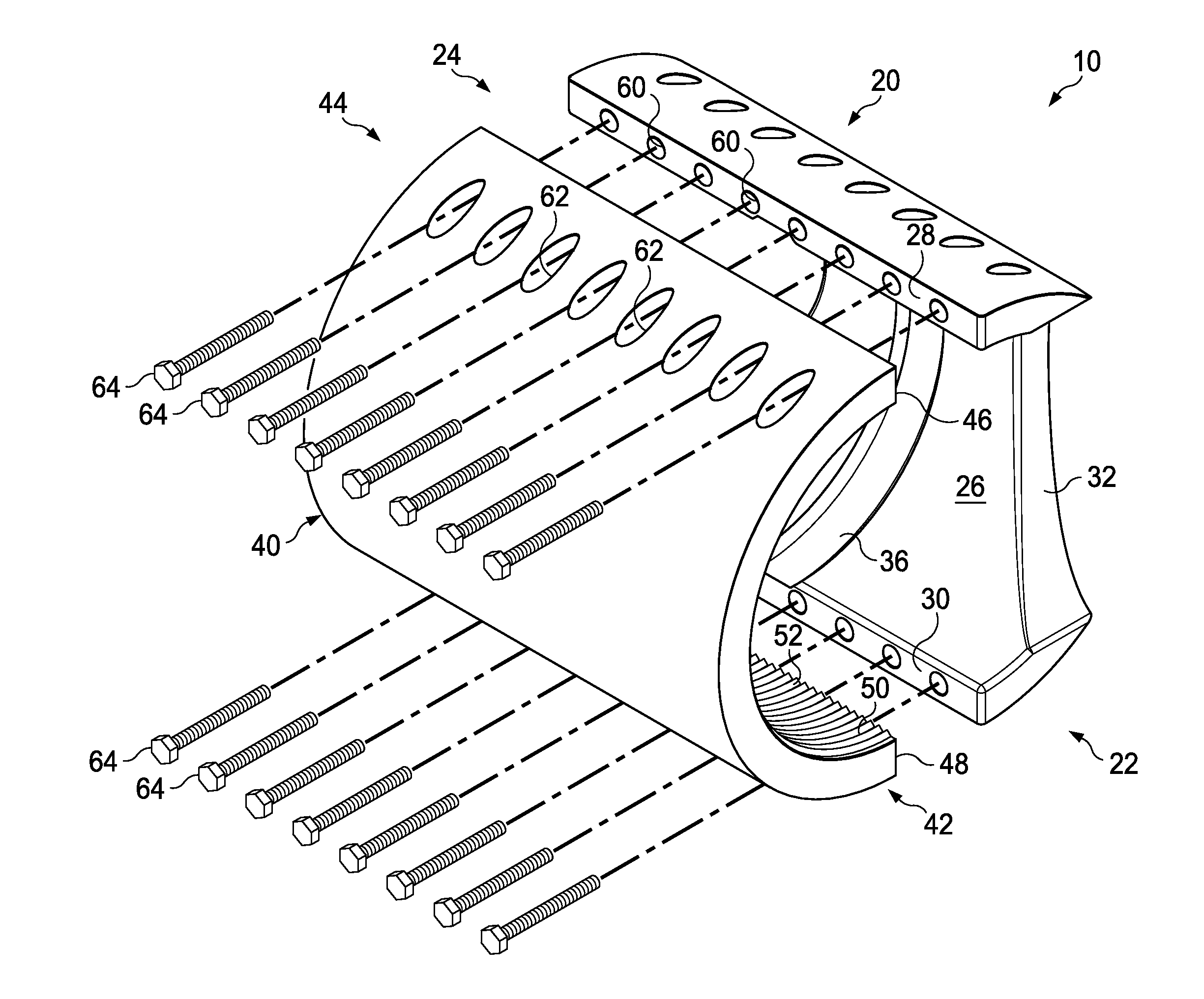
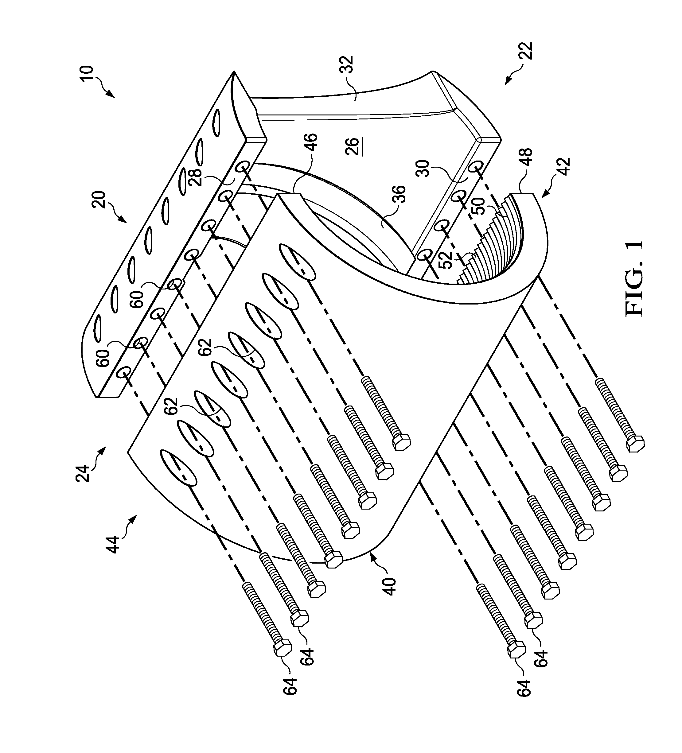
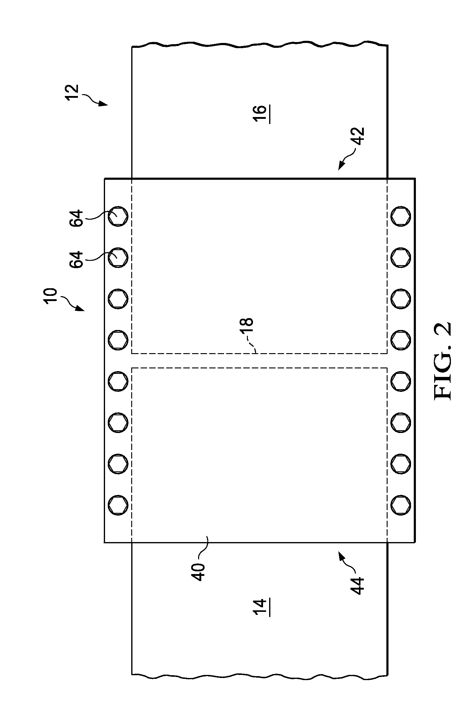
Referring now to FIGS. 1 and 2, shown is pipe clamp designated generally 10. Pipe clamp 10 is for affixing to pipe 12 (FIGS. 2, 9). Pipe 12 consists of first pipe segment 14 and second pipe segment 16. First pipe segment 14 and second pipe segment 16 are joined together via butt weld 18. Pipe clamp 10 is provided to protect butt weld 18 from excessive strain of a heat affected zone and ovallization, both induced by a coiling process of pipe 12, as shown in FIG. 9.

Pipe clamp 10 consists of inside clamp segment 20 (FIGS. 1, 3-5). Inside clamp segment 20 has a semi-cylindrical shape and has a first end 22 and a second end 24. Inside clamp segment 20 additionally has an inside surface 26, an upper lengthwise mating surface 28, and a lower lengthwise mating surface 30. First end 22 defines first stress relief area 32. Second end 24 defines second stress relief area 34 (FIGS. 3-5).

Inside clamp segment 20 preferably defines radial groove 36 for receiving butt weld 18 when inside clamp segm...


PUM


Abstract

A pipe clamp for affixing to a pipe subjected to bending to minimize fatigue for a butt weld in the pipe. The pipe clamp includes an inside clamp segment and an outside clamp segment each having a semi-cylindrical shape, a first end and a second end. An inside surface of the inside clamp segment is substantially smooth for permitting slippage of an outside surface of the pipe with respect to the inside surface of the clamp segment. The outside clamp segment has an inside surface that defines a friction element. The friction element is for gripping an outside surface of the pipe to which the outside clamp segment is affixed. A clamp mechanism is provided for securing the inside clamp segment to the outside clamp segment.

Description

FIELD OF THE INVENTIONThe invention relates to a pipe clamp. More particularly, the invention relates to a pipe clamp for locating over a butt weld in a length of pipe to be subjected to bending forces to protect against excessive strain in the weld area.BACKGROUND OF THE INVENTIONThe application area is the storage of natural gas (CNG) or other fluids or gases under pressure in pressure vessels comprised of very long lengths (generally over 1 km and under 30 km) of steel pipe. For practical management, these lengths of pipe are coiled on a steel spool by a simple winding process. The result is termed a “Coselle®”. Many Coselles® may be installed in the hold of a ship. A Coselle® carrying ship loads gas in a first port and discharges in a second port. A Coselle® carrying ship may make ˜60 cycles per year. The pressurizing and de-pressurizing associated with the loading and unloading of gas induces major stress changes in the steel of the Coselles®, which could possibly result in fat...

Claims


Application Information

Patent Timeline
IPC IPC(8): F16L25/00
CPCF16L13/0236F16L57/02F17C1/02F17C13/00F17C2203/011
Inventor FITZPATRICK, PATRICK JOHN
Owner SEA NG CORP
Why Eureka
Try Eureka