Connecting method and structure of crane beam for self adaptable column sedimentation

A technology for connecting structures and crane girders, applied in the direction of supporting structures, load hanging components, transportation and packaging, etc., can solve the problems of large difference in compressibility of soil layers, difficulty in adjusting foundation settlement to the same level, etc., and achieve good vertical deformation effect

Inactive Publication Date: 2005-05-11
GUIYANG AL-MG DESIGN & RES INST
View PDF0 Cites 14 Cited by
  • Summary
  • Abstract
  • Description
  • Claims
  • Application Information

AI Technical Summary

Problems solved by technology

In the design of industrial plants, it is often encountered that the same plant is located in different geological units. For example, one section of the plant is located on a high fill area (highly compressible backfill), and another section may be located on a well-conditioned geological area. It is very difficult to select the same bearing layer in the excavation area (undisturbed old soil layer with less compressibility)
In order to save the foundation investment, the foundation form can be selected by unit according to different geological conditions. However, when two units adopt different foundation forms, due to the large difference in the compressibility of the two soil layers, the two adjacent columns of the two units It is difficult to adjust the foundation settlement to be consistent, which requires the crane beams of the two unit joints to have a better ability to adapt to vertical deformation at the nodes at both ends. Obviously, the large nodes in the national standard atlas have been difficult to adapt to

Method used


Image

  • Connecting method and structure of crane beam for self adaptable column sedimentation
  • Connecting method and structure of crane beam for self adaptable column sedimentation
  • Connecting method and structure of crane beam for self adaptable column sedimentation

Examples


Embodiment Construction

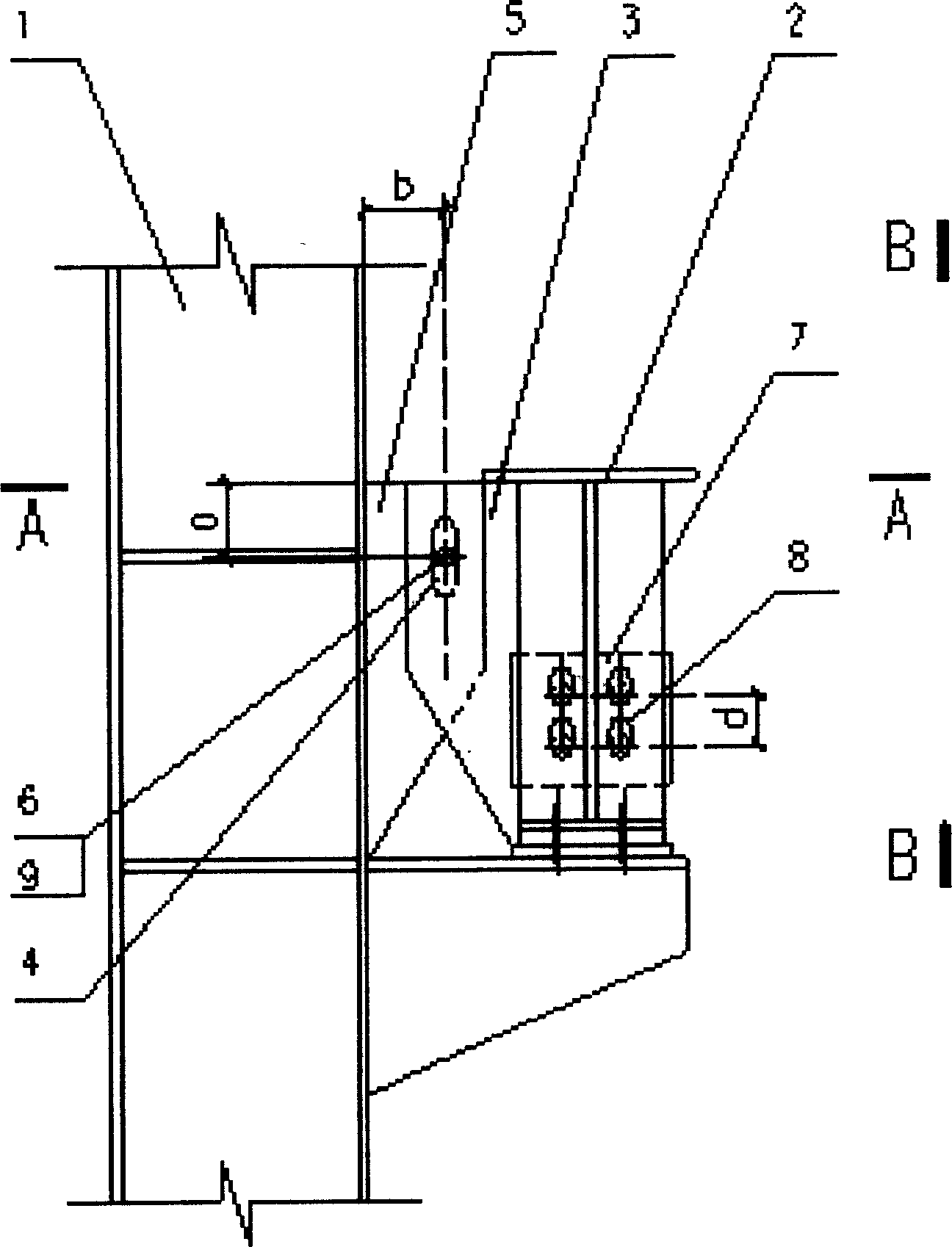
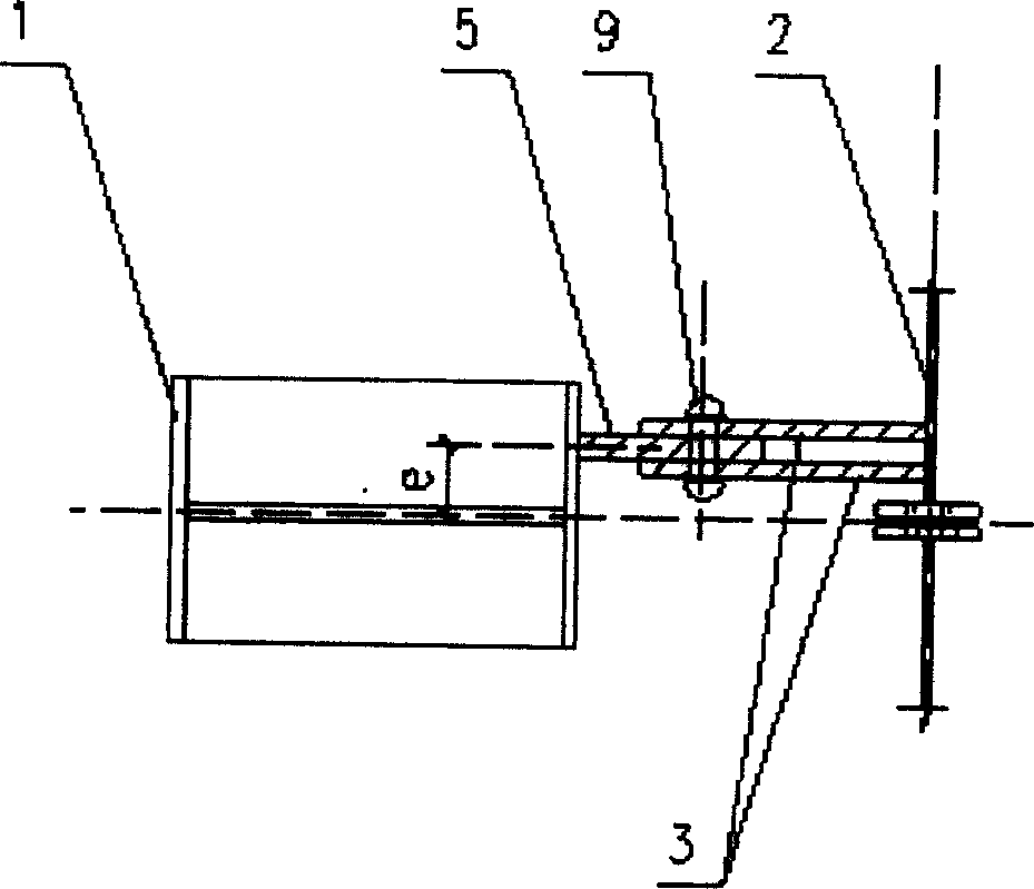
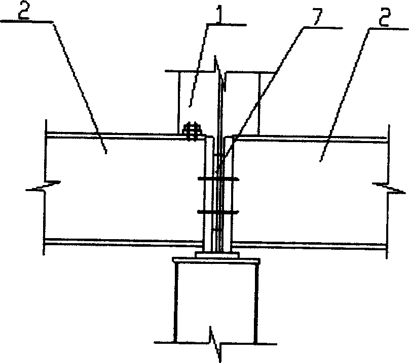
[0011] Embodiment of the present invention: open a vertical oval hole (4) on two steel plates (3), respectively weld the two steel plates (3) on the steel crane beam (2), and open the two steel plates (3) on the splint (5) A circular hole (6), the clamping plate (5) is welded on the factory building column (1) and the clamping plate (5) is placed in the middle of two steel plates (3), so that the circular hole (6) and the vertical oval hole ( 4) overlap, then insert a pin (9) in the circular hole (6) to connect them together; open a vertical ellipse on the connecting plate (7) of the crane beam (2) connecting the adjacent crane beam hole (8), and the bolts are inserted into the vertical oval hole (8). When connecting, the vertical distance a between the center of the pin (9) and the top of the steel crane girder (2) is 100 mm to 300 mm, and the distance b from the side of the factory column (1) is 60 mm to 300 mm. The center of the pin (9) The deviation distance e from the ce...


PUM


Abstract

A crane beam connecting method and structure adaptive to the settling of factory building columns features that the flexible connection able to move up or down is used between the said column and crane beam and between crane beams. A steel plate with vertical elliptical hole is fixed to the crane beam. A clamping plate with circular hole is fixed to the vertical column of factory building. Said steel plate and clamping plate are linked via pin.

Description

Technical field: [0001] The invention relates to a crane girder connection method and structure adaptive to the settlement of factory building columns in industrial factory building design. Background technique: [0002] At present, the connection design between the crane beam and the factory building column in the industrial factory building generally adopts the connection sample in the current national standard atlas "00G514". The upper flange of the crane girder and the factory building column are connected by horizontal steel plates, and the horizontal and horizontal braking force of the crane is transmitted to the column through welding and bolts. Since the vertical deformation of the horizontal steel plate is limited, the crane girder is also subject to great restrictions when there is vertical displacement, so it can only adapt to the small vertical displacement of the support. When the vertical displacement exceeds a certain limit, the node is not applicable. In th...

Claims


Application Information

Patent Timeline
Patent Type & Authority Applications(China)
IPC IPC(8): B66C6/00
Inventor 高晰潘晓临段建华陆欣邓中华徐丽王茜
Owner GUIYANG AL-MG DESIGN & RES INST
Why Eureka
Try Eureka