A portable electric trolley for a crane
A technology of electric trolleys and cranes, which is applied in the direction of load-bearing blocks, traveling mechanisms, load-hanging components, etc., can solve the problems of impact, waste, and rail gnawing of operating mechanisms, and achieve vertical deformation, large maximum lifting height, and improved The effect of lift height
- Summary
- Abstract
- Description
- Claims
- Application Information
AI Technical Summary
Problems solved by technology
Method used
Image
Examples
Embodiment 1
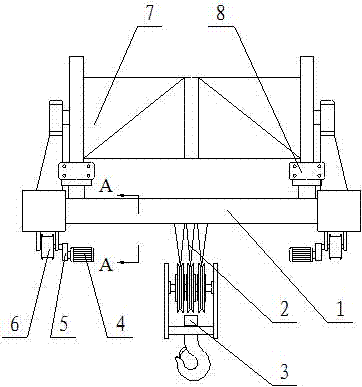
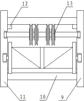
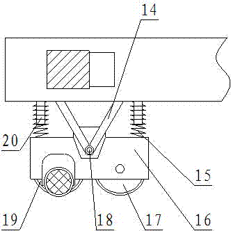
[0018] Such as Figure 1-3 As shown, a portable electric trolley of a crane includes a trolley frame 1. The trolley frame 1 consists of a left traveling frame 11, a right traveling frame 9 and a vehicle between the left traveling frame 11 and the right traveling frame 9. The support connecting rod 10 is composed of the left traveling frame 11 and the right traveling frame 9 and the support connecting rod 10 are provided with a technical square steel 12 on the upper surface of the trolley frame 1 is provided with an outer rotor motor 7, the Both ends of the outer rotor motor 7 are respectively provided with brakes 8. The outer surface of the outer rotor motor 7 is wound with a steel wire rope 2, and the steel wire rope 2 is connected to a hook group 3 through a fixed pulley group 13. 13 is set on the upper surface of the trolley frame 1, the lower surface of the left walking frame 11 and the right walking frame 9 are provided with a V-shaped frame 14 near the two ends, and the l...
Embodiment 2
[0021] Such as Figure 1-3 As shown, a portable electric trolley of a crane includes a trolley frame 1. The trolley frame 1 consists of a left traveling frame 11, a right traveling frame 9 and a vehicle between the left traveling frame 11 and the right traveling frame 9. The support connecting rod 10 is composed of the left traveling frame 11 and the right traveling frame 9 and the support connecting rod 10 are provided with a technical square steel 12 on the upper surface of the trolley frame 1 is provided with an outer rotor motor 7, the Both ends of the outer rotor motor 7 are respectively provided with brakes 8. The outer surface of the outer rotor motor 7 is wound with a steel wire rope 2, and the steel wire rope 2 is connected to a hook group 3 through a fixed pulley group 13. 13 is set on the upper surface of the trolley frame 1, the lower surface of the left walking frame 11 and the right walking frame 9 are provided with a V-shaped frame 14 near the two ends, and the l...
PUM
 Abstract
Description
Claims
Application Information
 - R&D
- Intellectual Property
- Life Sciences
- Materials
- Tech Scout
- Unparalleled Data Quality
- Higher Quality Content
- 60% Fewer Hallucinations
Browse by: Latest US Patents, China's latest patents, Technical Efficacy Thesaurus, Application Domain, Technology Topic, Popular Technical Reports.
© 2025 PatSnap. All rights reserved.Legal|Privacy policy|Modern Slavery Act Transparency Statement|Sitemap|About US| Contact US: help@patsnap.com


