Air outlet assembly for a vehicle

A technology for ventilation outlets and motor vehicles, which is applied to vehicle components, heating/cooling equipment, transportation and packaging, etc., and can solve problems such as susceptibility to interference, high cost, and unstable structure

Inactive Publication Date: 2005-06-15
FORD GLOBAL TECH LLC
View PDF1 Cites 12 Cited by
  • Summary
  • Abstract
  • Description
  • Claims
  • Application Information

AI Technical Summary

Problems solved by technology

The problem with such ventilation outlets is that the groove control part of the guide vanes located outside the housing frame is

Method used


Image

  • Air outlet assembly for a vehicle
  • Air outlet assembly for a vehicle
  • Air outlet assembly for a vehicle

Examples


Embodiment Construction

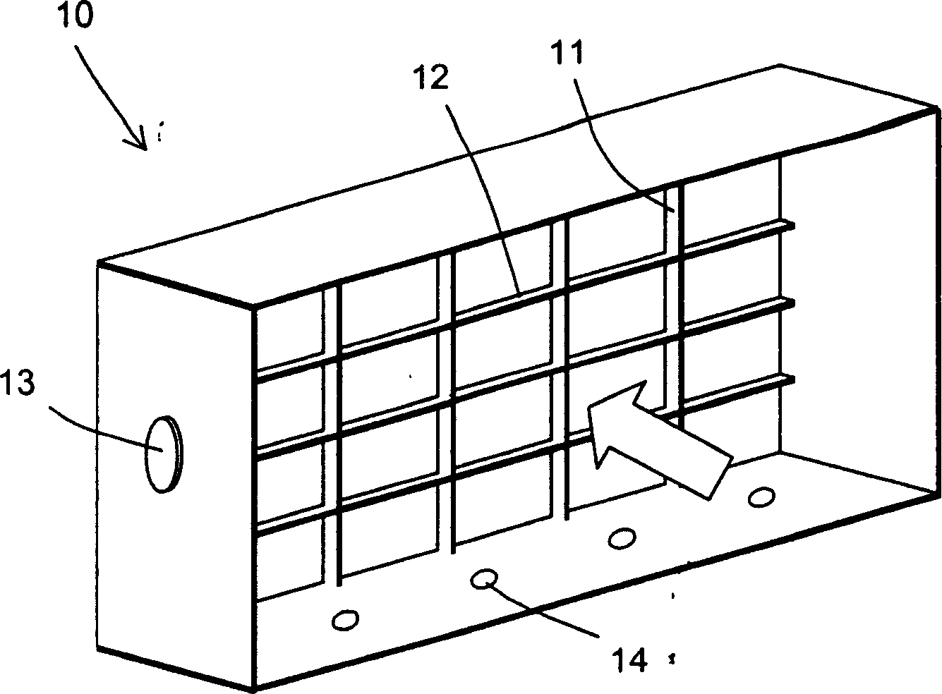
[0027] figure 1 A housing frame 10 according to the invention for an air vent of a motor vehicle is shown schematically. The housing frame 10 is substantially in the shape of a rectangular frame and has an intake side (front) and an exhaust side (rear). The direction of air flow when using the vent is indicated by a boxed arrow. The entire ventilation opening including the housing frame is preferably made of plastic.

[0028] The exhaust side facing the passenger compartment is covered in the example shown by a grid consisting of a plurality of vertical baffles 11 and a plurality of horizontal baffles 12 . These air deflector vanes 11 , 12 can be adjusted in a manner not shown and / or have operating elements such as knobs or sliding elements, by means of which components (guide vanes, slots) to be described below can be moved.

[0029] Also in figure 1 One of the two hinge pins 13 opposite to each other can be seen in the drawing, by means of which the housing frame 10 as a...


PUM


Abstract

The invention relates to an adjustable ventilation outlet for a motor vehicle, which has a plurality of guide vanes (20a-20e) pivotable about parallel axes (23). These guide vanes are each engaged with guide slots (32a-32e) of a channel plate (30) by means of pegs, whereby the relative orientation of the guide vanes can be changed by movement of the channel plate. Independently of this, the angular orientation of the guide vanes can advantageously be adjusted synchronously via a slide ( 15 ).

Description

technical field [0001] The invention relates to an adjustable air vent for a motor vehicle, which has a housing frame and a number of guide vanes which are rotatably arranged in the housing frame. Background technique [0002] A ventilation outlet for motor vehicles of the type mentioned at the outset is known from US 5 063 833 . In this case, a series of guide vanes are mounted rotatably about mutually parallel pivot axes in a box-shaped housing frame. On the outside of the housing, the rods connected to the shafts of the guide vanes are guided into a channel plate with pegs provided at their ends, each peg being inserted into its guide groove. A motor-controlled displacement of the slot plate in a direction perpendicular to the pivot axis of the guide vanes moves the pegs along predetermined paths in the guide slots, whereby the guide vanes each acquire an individual orientation dependent on the position of the slot plate. The problem with such ventilation outlets is tha...

Claims


Application Information

Patent Timeline
IPC IPC(8): B60H1/34
CPCB60H1/345B60H2001/3471
Inventor 迪特马尔·菲舍尔
Owner FORD GLOBAL TECH LLC
Why Eureka
Try Eureka