Aerialwind power generation system and method

a power generation system and wind turbine technology, applied in the direction of electric generator control, machines/engines, transportation and packaging, etc., can solve the problems of increasing the need for cost competitive methods and apparatuses for harnessing renewable energy sources, increasing the and increasing the capital cost of wind turbines relative to power generated, so as to increase the power generated

Inactive Publication Date: 2007-03-13
OLSON GAYLORD G
View PDF22 Cites 136 Cited by
  • Summary
  • Abstract
  • Description
  • Claims
  • Application Information

AI Technical Summary

Benefits of technology

[0009]Another aerial power generation system includes a plurality of wind powered driven elements connected by tow lines to spaced attachment points on a revolving apparatus that drives a means for generating power. A means for changing the driven elements between high force configurations and low force configurations changes each driven element to high force configurations when the respective attachment point is moving downwind and to low force configurations when the respective attachment point is moving upwind to cause rotation of the revolving apparatus. The driven elements are flown in a pattern at a high speed perpendicular to the tow line, when in the high force configurations, to increase the power generated.

Problems solved by technology

As fossil fuels become depleted and more expensive, the need for cost competitive methods and apparatus for harnessing renewable energy sources increases.
Windmills (or wind turbines) are currently being used to generate electricity and to drive pumps, however the cost to generate electricity with a windmill is still more expensive than the cost of electricity generated from fossil fuels.
Windmills have a high capital cost relative to power generated.
The challenge with wind power generation is to convert the linear power of the wind to rotary motion to drive an electrical generator or a pump.
These aerial windmills are relatively heavy and require long, heavy electrical cables to transmit the generated power to ground level.

Method used


Image

  • Aerialwind power generation system and method
  • Aerialwind power generation system and method
  • Aerialwind power generation system and method

Examples


Embodiment Construction

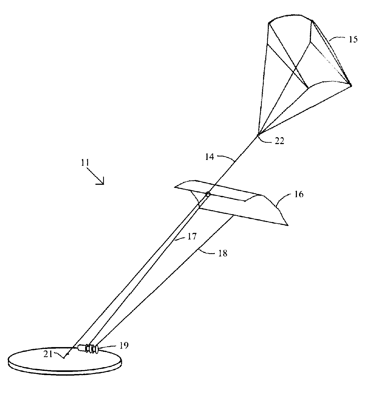
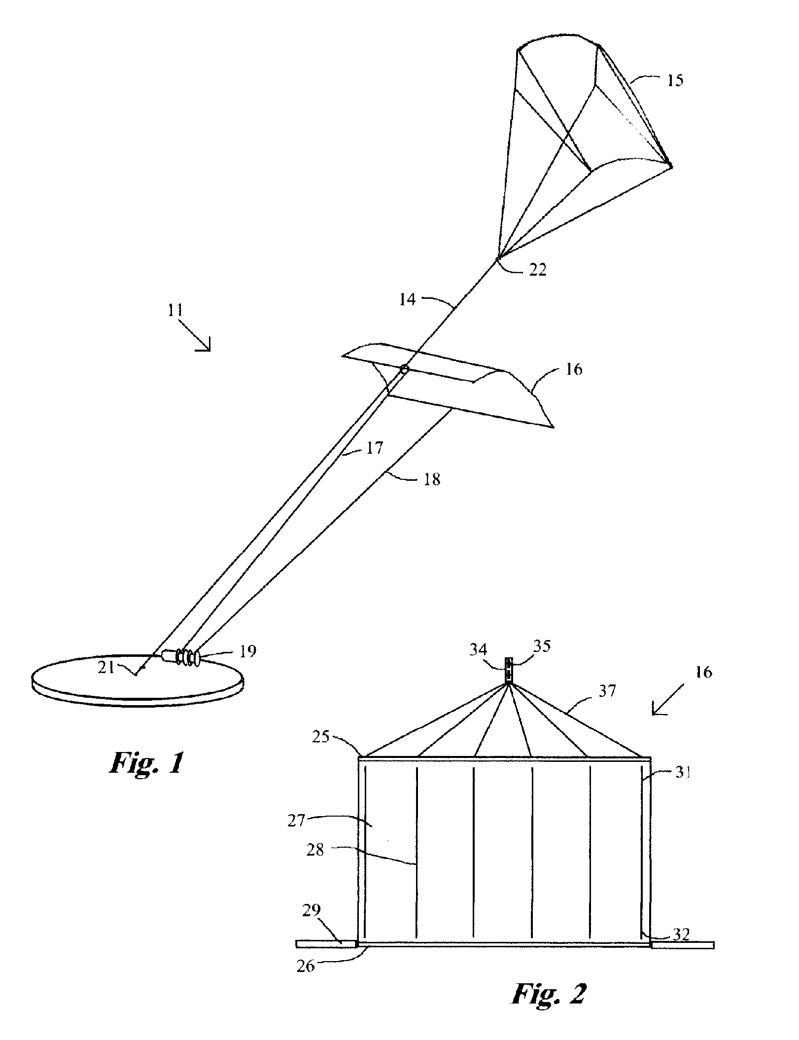
[0044]Referring now to FIG. 1, an aerial wind power generation system 11 embodying features of the present invention includes a first guide line 14, a first support body 15, a driven element 16, a first tow line 17, a second tow line 18 and a means for generating power 19. The first guide line 14 has a first end 21 that is tethered at the ground or to a structure, and the first guide line 14 extends skywardly at a selected elevation angle to a spaced second end 22 that is attached to the first support body 15. The first support body 15 is an aircraft that is lifted by the wind, such as a kite as shown, or a lighter than air aircraft, such as a blimp or a balloon. Preferably the lift of the first support body 15 can be varied to maintain the elevation angle of the first guide line 14.

[0045]The driven element 16 is slidably attached or mounted on the first guide line 14. The driven element 16 is a kite, sail, airfoil or other element that generates both drag and lift from the wind. Th...


PUM


Abstract

An aerial power generation system includes a guide line supported by a support body. Wind driven elements are configured and shaped to provide maximum force from both lift and drag during the downwind phase of operation and minimum force during the upwind phase. The guide lines add stability to the system and provide better control over angular orientation and direction of motion. Power transfer is through one or more tow lines connected from the driven elements to power generation devices on the ground. Another embodiment of the aerial power generation system includes a revolving apparatus and two or more wind powered driven elements connected by tow lines to the revolving apparatus. The method includes changing the driven elements between high and low force configurations for downwind and upwind operation, and flying the driven elements in a selected pattern perpendicular to the tow line.

Description

[0001]This application is a continuation-in-part of Ser. No. 11 / 164,512 filed Nov. 28, 2005TECHNICAL FIELD[0002]The present invention relates to power generation and more particularly to systems and methods that convert wind energy acting on aerial wind driven elements to rotary or electrical power.BACKGROUND ART[0003]As fossil fuels become depleted and more expensive, the need for cost competitive methods and apparatus for harnessing renewable energy sources increases. The wind was long used for powering sailing ships and windmills, but the advent of steam engines or turbines, internal combustion engines, and gas turbines provided cheaper, more convenient energy sources. Less expensive and more efficient apparatus and methods for utilizing wind power would now be beneficial.[0004]Windmills (or wind turbines) are currently being used to generate electricity and to drive pumps, however the cost to generate electricity with a windmill is still more expensive than the cost of electrici...

Claims


Application Information

Patent Timeline
Patent Type & Authority Patents(United States)
IPC IPC(8): F03D9/00B64C31/06
CPCF03D5/00F03D5/04F03D5/06Y02E10/725F05B2240/921F05B2240/94Y02E10/70F05B2240/92Y02E10/72
Inventor OLSON, GAYLORD G.
Owner OLSON GAYLORD G
Why Eureka
Try Eureka