Method and apparatus for thermal, mechanical, and electrical optimization of a solid-oxide fuel cell stack

a solid-oxide fuel cell and stack optimization technology, applied in the field of solid-oxide fuel cells, can solve the problems of reducing stack durability, high stress within the stack, and sensitive to uneven flow distribution, so as to improve fuel efficiency and reduce thermal stress , the effect of increasing electrical power generation

Inactive Publication Date: 2006-08-03
DELPHI TECH INC
View PDF7 Cites 51 Cited by
  • Summary
  • Abstract
  • Description
  • Claims
  • Application Information

AI Technical Summary

Benefits of technology

[0016] A sub-stack module in accordance with the invention comprises first and second sub-stacks arranged in flow series as just described with a first heat exchanger between the stacks and a second heat exchanger ahead of the first stack. A plurality of sub-stack modules may be ganged in flow parallel and connected in electrical series to provide any desired electrical voltage. There can also be connected electrically in parallel or be run electrically independent from one another. In such arrangements, it can be useful to provide an auxiliary cooling unit whose output is controllably divided as by a plenum and valving among the plurality of modules such that the thermal operating conditions of all sub-stacks and all modules are optimal.
[0017] The result of dividing the number of cells into a plurality of stacks, wherein the exhaust of one stack becomes the supply for the next stack, is that fuel efficiency is improved, thermal stresses are reduced, electrical power generation is increased, and configurational flexibility is enhanced.

Problems solved by technology

This flow scheme is sensitive to uneven flow distribution at low anode flow rates.
High temperature gradients produce high stresses within the stack and can reduce stack durability.
Temperature gradients through the traditional stack may be reduced through increased cathode air massflow, but this results in reduced air utilization for the fuel cell system and a resulting loss of system efficiency.

Method used


Image

  • Method and apparatus for thermal, mechanical, and electrical optimization of a solid-oxide fuel cell stack
  • Method and apparatus for thermal, mechanical, and electrical optimization of a solid-oxide fuel cell stack
  • Method and apparatus for thermal, mechanical, and electrical optimization of a solid-oxide fuel cell stack

Examples


example 1

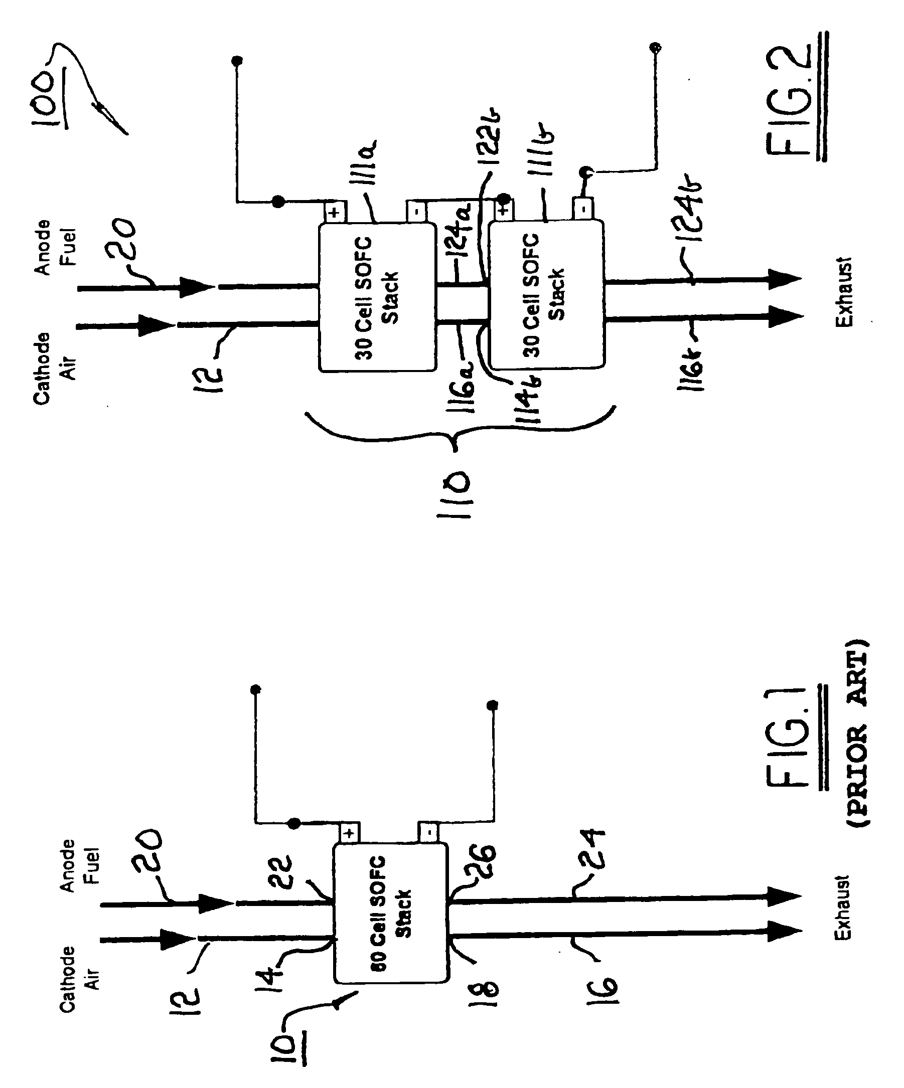
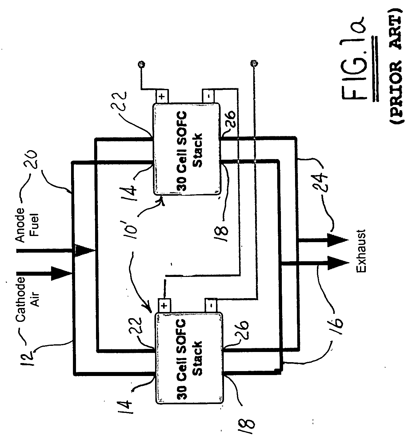
[0032] An SOFC stack configured in accordance with FIG. 1 was operated at a current of 0.9 amps / cm2. With a temperature differential across the stack of 150° C. (inlet temperature 650° C., outlet temperature 800° C.), the stack produced 4810 watts of electricity at 0.74 volts / cell, fuel utilization was 43%, stack efficiency was 21.8%, and an additional 1136 watts of heat was released within the stack.

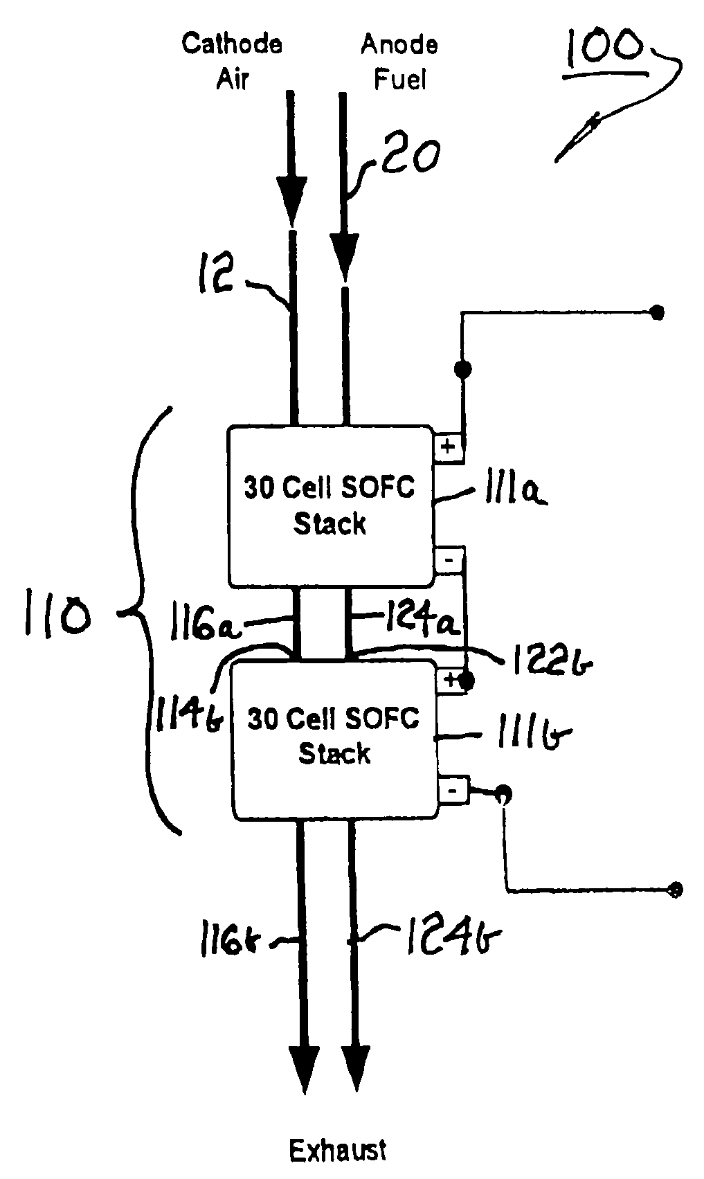
[0033] Referring to FIG. 2, in a first embodiment 100 in accordance with the invention, a fuel cell stack 110 having a plurality of individual fuel cell elements, for example, 60 cells as in prior art stack 10, is divided into a plurality of sub-stacks, for example, two sub-stacks 111a,111b each containing 30 fuel cell elements, the two sub-stacks being connected in series electrically. Other numbers of sub-stacks are fully comprehended by the invention, and the numbers of fuel cells may or may not be distributed equally among the sub-stacks.

[0034] In accordance with the invention, th...

example 2

[0035] An SOFC stack configured in accordance with FIG. 2 was operated at a current of 0.9 amps / cm2.

[0036] Sub-stack 111a was operated with a temperature differential of 100° C. (650° C. inlet temperature, 750° C. outlet temperature) and produced 2359 watts of electricity at 0.72 volts / cell. Fuel utilization was 21.8%, stack efficiency was 10.7%, and only 177 watts of heat were rejected into the stack. Note that this is a much lower fuel utilization and stack efficiency than for prior art stack 10.

[0037] Sub-stack 111b had an inlet temperature of 750° C. and an outlet temperature of 850° C. Sub-stack 111b produced 2589 watts of electricity at 0.79 volts / cell. Fuel utilization was 28% and the stack efficiency was 15%. The reaction was slightly endothermic, requiring 138 watts of energy from the stack.

[0038] Advantages of the novel stack configuration in accordance with the invention (FIG. 2) vs. the prior art configuration (FIG. 1): [0039] a) the novel configuration produced more ...


PUM

PropertyMeasurementUnit
temperaturesaaaaaaaaaa
temperatureaaaaaaaaaa
outlet temperatureaaaaaaaaaa

Abstract

A solid-oxide fuel cell stack assembly comprising a plurality of sub-stacks, preferably two sub-stacks each containing one-half the total number of fuel cells. Cathode air and fuel gas are passed through the first sub-stack, wherein they are partially reacted and also heated. The exhaust cathode air and the exhaust fuel gas from the first sub-stack are directed to the respective inlets of the second sub-stack, becoming the supply cathode air and fuel gas therefor. A first heat exchanger in the flow paths between the sub-stacks and a second heat exchanger ahead of the sub-stacks can help to balance the performance of the two stacks. The result of dividing the number of cells into a plurality of sub-stacks, wherein the exhaust of one sub-stack becomes the supply for the next sub-stack, is that fuel efficiency and utilization are improved, thermal stresses are reduced, and electrical power generation is increased.

Description

TECHNICAL FIELD [0001] The present invention relates to fuel cells; more particularly, to solid-oxide fuel cells; and most particularly, to arrangements for optimizing the operating conditions, longevity, efficiency, fuel utilization, and electrical output of a solid-oxide fuel cell stack. BACKGROUND OF THE INVENTION [0002] Fuel cells for combining hydrogen and oxygen to produce electricity are well known. A known class of fuel cells includes a solid-oxide electrolyte layer through which oxygen anions migrate; such fuel cells are referred to in the art as “solid-oxide” fuel cells (SOFCs). [0003] In some applications, for example, as an auxiliary power unit (APU) for a transportation application or a stationary power unit (SPU) for a stationary application, an SOFC is preferably fueled by “reformate” gas, which is the effluent from a catalytic liquid or gaseous hydrocarbon oxidizing reformer, also referred to herein as “fuel gas”. Reformate typically includes amounts of carbon monoxi...

Claims


Application Information

Patent Timeline
Patent Type & Authority Applications(United States)
IPC IPC(8): H01M8/24H01M8/12H01M8/04
CPCH01M8/04007H01M8/04089H01M8/04097H01M8/249H01M2008/1293Y02E60/50Y02E60/525
Inventor MACBAIN, JOHN A.KELLY, SEAN M.MERGLER, CHRISTOPHER
Owner DELPHI TECH INC
Why Eureka
Try Eureka