Wind turbine generator and method of estimating wind direction in wind turbine generator

a wind turbine generator and wind turbine technology, applied in the direction of electric generator control, machines/engines, mechanical equipment, etc., can solve the problems of unbalanced load applied to the wind turbine generator, the output power of the generator of the wind turbine generator decreases, etc., and achieves the effect of improving the power generation performance of the wind turbine generator

Active Publication Date: 2011-05-05
MITSUBISHI HEAVY IND LTD
View PDF18 Cites 51 Cited by
  • Summary
  • Abstract
  • Description
  • Claims
  • Application Information

AI Technical Summary

Benefits of technology

[0012]In this manner, according to the present invention, by estimating the actual direction of wind blowing against the wind turbine generator, yaw control can be performed such that the nacelle faces into the actual main wind direction. Thus, the power generating performance of the wind turbine generator improves.

Problems solved by technology

Since the rotational energy given by the wind decreases as the deviation with the wind direction increases, there is a problem in that the generator output power of the wind turbine generator decreases because of the deviation with the wind direction.
Furthermore, there is also a problem in that an unbalanced load is applied to the wind turbine generator because of the deviation with the wind direction.

Method used


Image

  • Wind turbine generator and method of estimating wind direction in wind turbine generator
  • Wind turbine generator and method of estimating wind direction in wind turbine generator
  • Wind turbine generator and method of estimating wind direction in wind turbine generator

Examples


first embodiment

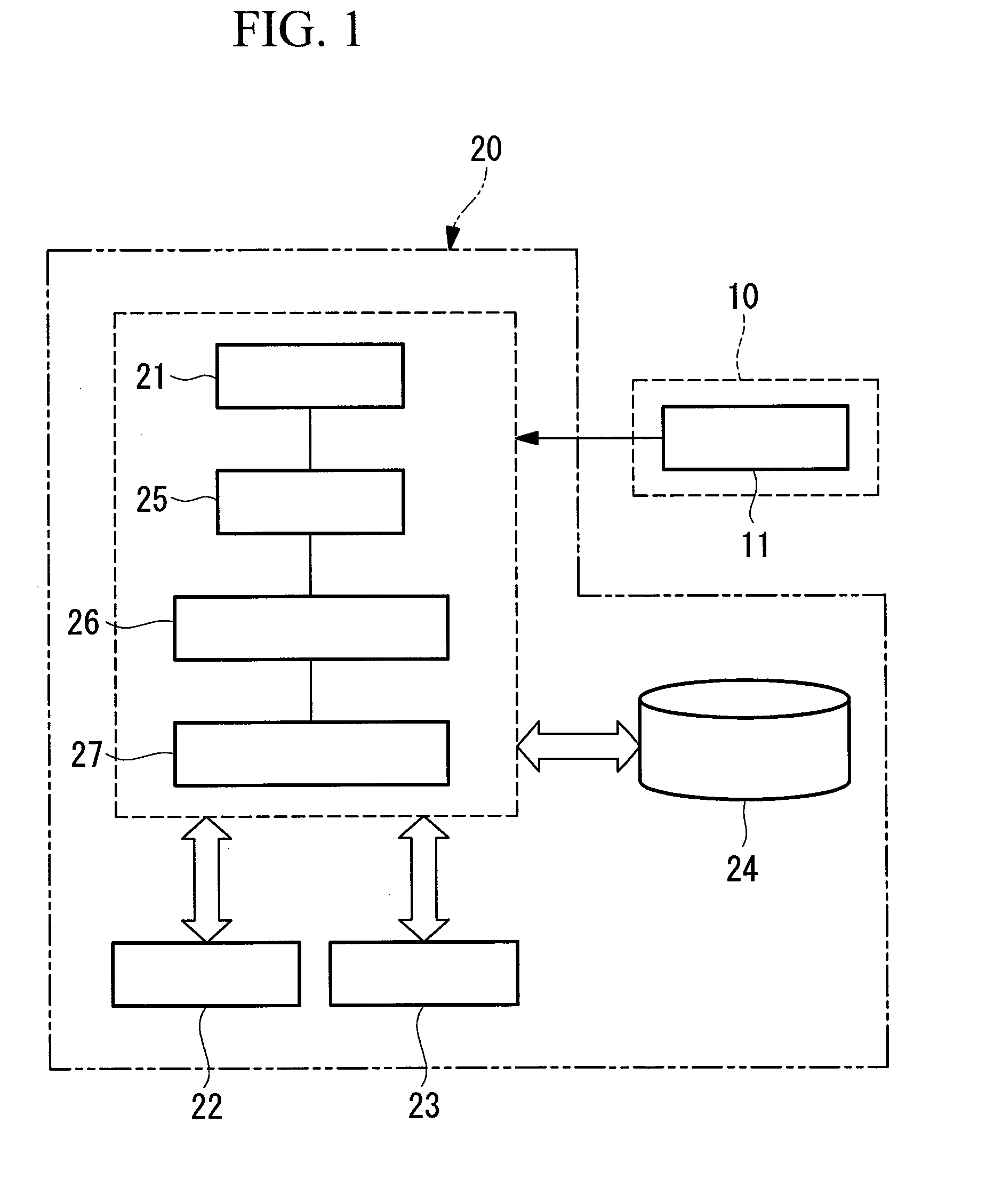
[0026]FIG. 1 is a block diagram showing the schematic configuration of a wind turbine generator of the present invention. As shown in FIG. 1, the wind turbine generator includes an anemoscope 11, serving as wind direction detecting means, on the top of a nacelle 10. This anemoscope detects the direction of wind blowing against the wind turbine generator and outputs the detected wind direction to a calculation unit 20.

[0027]The calculation unit 20 performs calculation to estimate the actual wind direction and includes a CPU (central processing unit) 21 that performs various processing; a ROM (Read Only Memory) 22, which is a memory that allows only reading operations and stores a basic program and the like; a RAM (Random Access Memory) 23, which is a memory that allows both reading and writing operations and serves as a work area for the CPU 21; and a storage device 24 that stores programs and various data.

[0028]The calculation unit 20 also includes a wind direction assuming unit 25 ...

second embodiment

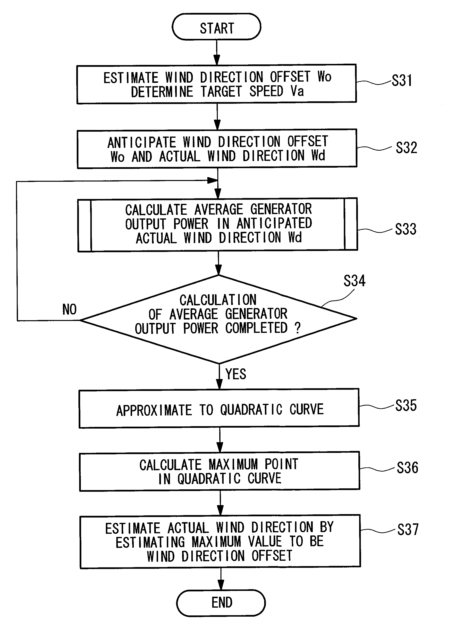
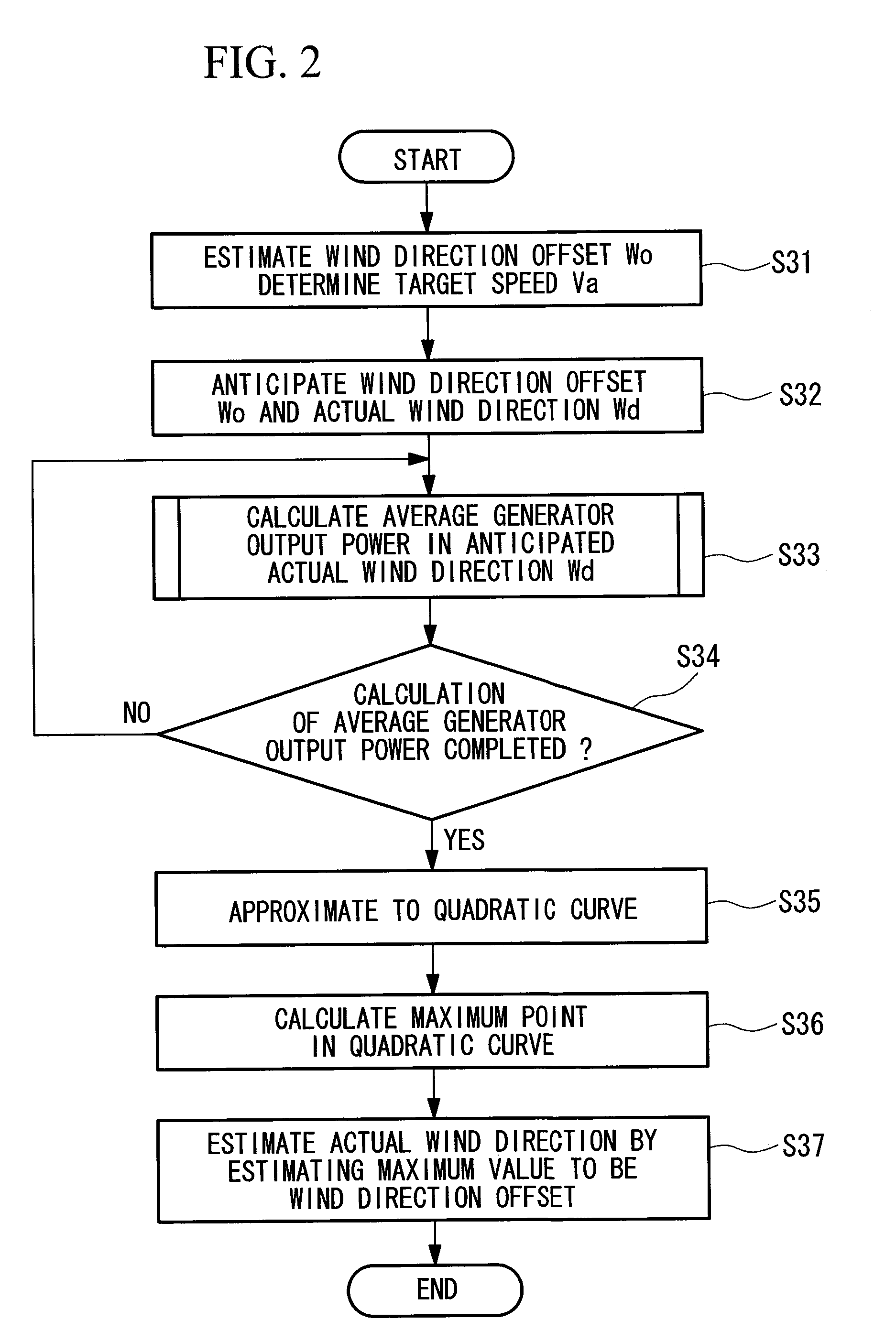
[0042]Next, a second embodiment of the present invention will be described using FIGS. 6 and 7.

[0043]A wind turbine generator according to this embodiment has the same configuration as the first embodiment, but processing steps of the method of estimating wind direction are different. In the above-described first embodiment, a quadratic approximated curve is generated by deriving an approximate expression. In this embodiment, processing to generate an approximated curve using a gradient method will be described. FIG. 6 is a flowchart showing processing steps in the method of estimating wind direction according to this embodiment. Also in this processing step, described below, the target speed Va with respect to which the wind direction offset value Wo is estimated is determined in advance, and the average generator output power at this speed Va is calculated.

[0044]In step S51 in FIG. 6, the wind direction assuming unit 25 sets an initial value Wo(1) of the wind direction offset valu...


PUM


Abstract

Yaw control is performed such that a nacelle faces into an actual main wind direction. The actual wind direction is estimated by detecting the main wind direction with an anemoscope (wind direction detecting means), assuming the actual wind direction by assuming a wind direction offset value, which is a deviation between the main wind direction and the actual wind direction, which is a direction of wind which blows in actual use, at a predetermined wind speed with a wind direction assuming unit (wind direction assuming means), calculating an average generator output power for a predetermined period of time in the assumed actual wind direction with an average-generator-output-power calculation unit (average-generator-output-power calculation means), approximating the average generator output power with respect to the assumed wind direction offset value to a quadratic curve with an actual wind direction estimation unit (actual wind direction estimation means), and estimating the wind direction offset value at the time when the average generator output power is the maximum in the approximated quadratic curve to be an actual offset value.

Description

TECHNICAL FIELD[0001]The present invention relates to wind turbine generators, and, more specifically, to wind turbine generators in which the orientation of nacelles is variably controlled so as to follow the wind direction.BACKGROUND ART[0002]Up-wind type wind turbine generators have a rotor head, which includes a nacelle mounted on a tower and blades attached thereto, and a generator driven by shaft output power of the rotor head. In the wind turbine generators having such a configuration, the blades receive wind power, and the blades and the rotor head are rotated, which is transmitted to the generator. Thus, using the shaft output power obtained by converting wind power to rotary power as the driving source of the generator, power generation using wind power as the motive power of the generator can be performed.[0003]In the wind turbine generators of this type, the generator output power varies depending on the wind speed and the wind direction. Therefore, U.S. Pat. No. 6,320,2...

Claims


Application Information

Patent Timeline
Patent Type & Authority Applications(United States)
IPC IPC(8): H02P9/04
CPCF03D7/0204F03D7/042F05B2200/221Y02E10/723F05B2270/321F05B2270/335F05B2260/821Y02E10/72F03D7/04
Inventor HASHIMOTO, MASAYUKIWAKASA, TSUYOSHIMATSUSHITA, TAKATOSHI
Owner MITSUBISHI HEAVY IND LTD
Why Eureka
Try Eureka