
Solid polymer electrolyte fuel cell and method for manufacturing the same

a fuel cell and electrolyte technology, applied in the direction of cell components, final product manufacturing, sustainable manufacturing/processing, etc., can solve the problems of difficult system to supply hydrogen, poorly respond to the supply amount, and gas state of hydrogen supplied as a fuel

Active Publication Date: 2006-01-26
HONDA MOTOR CO LTD +1
View PDF2 Cites 51 Cited by
  • Summary
  • Abstract
  • Description
  • Claims
  • Application Information

AI Technical Summary

Benefits of technology

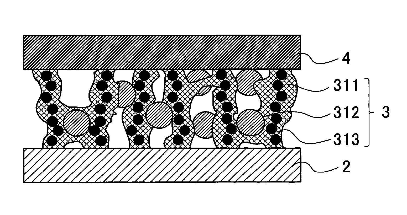
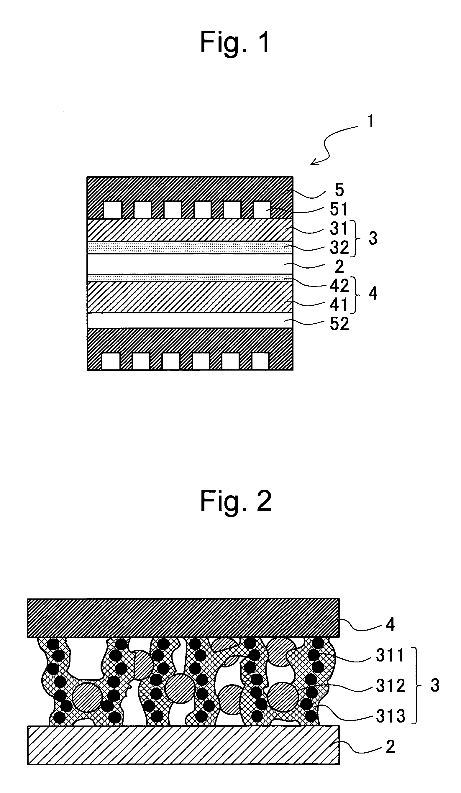
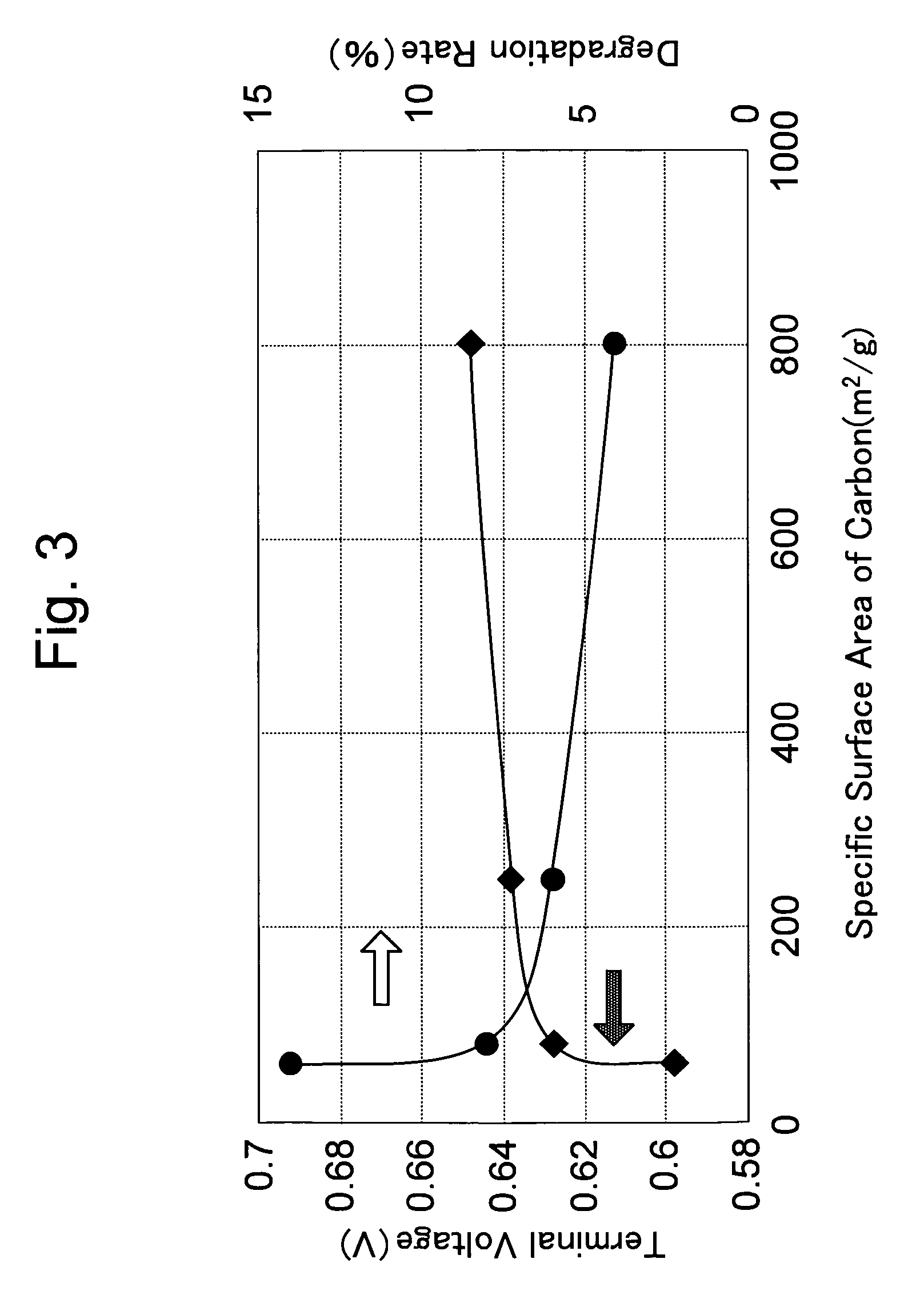
The present invention provides a solid polymer electrolyte fuel cell that can vary its output according to the demand load. The fuel cell has a high power generation performance and is durable even when faced with rapid changes in output due to fuel shortage. The fuel cell includes an electrode structure with a catalyst layer comprising an ion conductive material, a platinum powder and / or platinum alloy powder, and carbon. The carbon is a support for the electronic conduction path and helps to discharge water and oxygen generated by the reverse voltage. The specific surface area of the carbon is important for efficient gas and water discharge. The fuel cell also includes a separator for holding the electrodes, which can have a significant impact on the performance of the fuel cell.

Problems solved by technology

As in the case with a fuel cell direct connection system of FIG. 9B, the fuel cell 6 and the storage element 8 for storing electricity is directly connected in parallel to the motor 7 and mounted to a vehicle, it is necessary at the anode side to supply hydrogen flexibly corresponding to changes in the output generated according to changes in the acceleration of the vehicle, however, the hydrogen supplied as a fuel is in a state of gas, and poorly responds in controlling the amount of supply.
It is therefore difficult for the system to supply hydrogen corresponding to the increase in the amount of current, and to deal flexibly with the changes in the output.
As a result, fuel shortage arises temporarily in an electrode structure.
When the electrolysis of water occurs in the anode, it will cause a corrosion of the carbon used for the catalyst carrier in the catalyst layer which constitutes the anode, and will result in a deterioration of the performance.
The deterioration of the performance of the anode will lead to a deterioration of the power generation performance of the fuel cell as a whole.
The methods disclosed in Patent Documents 1 through 4 control the corrosion of carbon, however, does not fully satisfy the resistance property to the reverse voltage.
These methods are effective in the case of a temporary fuel shortage, however, in actual operation, speed fluctuation is conducted rapidly and repeatedly and the fuel shortage incurs, and resulting in the degradation of the power generation performance due to a development of corrosion reaction of carbon.

Method used


Image

  • Solid polymer electrolyte fuel cell and method for manufacturing the same
  • Solid polymer electrolyte fuel cell and method for manufacturing the same
  • Solid polymer electrolyte fuel cell and method for manufacturing the same

Examples


example

Example 1

Production of a Sample 1

Preparation of cathode electrode

[0050] 35 g of ion conductive polymer (trade name: Nafion SE2020, produced by Du Pont Kabushiki Kaisha), 10 g of platinum support carbon particles (TEC10E50E produced by Tanaka Kikinzoku Kogyo K.K.) in which carbon black and platinum were mixed at a weight ratio of 50:50, and a 2.5 g of crystalline carbon fiber (VGCF produced by Showa Denko K.K.) were mixed in isopropanol to make a cathode catalyst paste. The cathode catalyst paste was applied on the Teflon (FEP) sheet so that it contains 0.3 mg / cm2 of platinum and dried to form an electrode sheet A.

Preparation of Anode Electrode

[0051] In a 5 g of ion conductive polymers (trade name: Nafion SE2021, produced by Du Pont Kabushiki Kaisha) and 1 g of carbon black powder (Ketjenblack by Cabot Corp.), 9 g of catalyst powder Pt-Ru alloy powder, 5 g of pure water, and 10 g of 1-propanol was mixed to make an anode catalyst paste. The anode catalyst paste was applied on t...

example 2

Production of Sample 2

[0055] In 10 g of ion conductive polymers (Nafion SE2021) and 1 g of carbon black powder (Ketjenblack produced by Lion Akzo Co., Inc.), 1 g of crystalline carbon fiber (VGCF produced by Showa Denko K.K.), 8 g of catalyst powder Pt-Ru alloy powder, 5 g of pure water, and 10 g of 1 -propanol was mixed to make an anode catalyst paste. The anode catalyst paste was applied on the FEP sheet so that it contains 0.5 mg / cm2 of catalyst metal and dried to form an electrode sheet B. The electrode sheet B and the previously prepared electrode sheet A sandwiching the electrolyte membrane for transfer printing by way of a decal method to form CCM. The CCM was sandwiched by the previously water-repellent processed diffusion layer to form MEA.

example 3

Production of Sample 3

[0056] The sample was prepared in a similar way as in Example 2 except that 20 g of the ion conductive polymer (Nafion SE2021) was added.


PUM

PropertyMeasurementUnit
particle sizeaaaaaaaaaa
specific surface areaaaaaaaaaaa

Abstract

A solid polymer electrolyte fuel cell comprises: a plurality of electrode structures comprising an anode and a cathode, and polymer electrolyte membrane held between the anode and the cathode, and a plurality of separators for holding the respective electrode structures, with a fuel gas passage for supplying and discharging fuel gas containing hydrogen on a surface opposing the anode; and an oxidant gas passage for supplying and discharging oxidant gas on a surface opposing the cathode. The catalyst layer of the anode comprises a mixture of an ion conductive material, a platinum powder and / or platinum alloy powder and a carbon, the platium powder and / or platinum alloy powder and carbon substantially exist independently from each other, and the catalyst layer of the cathode comproses a metal support mixture in which the ion conductive material and the electro-conductive material having the supported catalyst material are mixed.

Description

INCORPORATION BY REFERENCE [0001] Priority is claimed on Japanese Patent Application No. 2004-209216, filed Jul. 15, 2004, and Japanese Patent Application No. 2005-111742, filed Apr. 8, 2005, the contents of which are incorporated herein by reference. [0002] 1. Field of the Invention [0003] The present invention is related to a solid polymer electrolyte fuel cell and a method for manufacturing thereof, in particular, a solid polymer electrolyte fuel cell in which the output varies according to a demand load. [0004] 2. Related Art [0005] A fuel cell uses hydrogen gas as a fuel gas and generates energy by an electrochemical reaction of hydrogen and oxygen. There are various types of fuel cells including a phosphoric acid fuel cell, a molten carbonate fuel cell, a solid electrolyte type fuel cell, and a solid polymer electrolyte fuel cell. Among these, a solid polymer electrolyte fuel cell can start operation at a normal temperature and can also provide higher output with small configu...

Claims


Application Information

Patent Timeline
Patent Type & Authority Applications(United States)
IPC IPC(8): H01M4/96H01M8/10H01M8/04H01M4/92H01M4/88B82Y99/00H01M4/86H01M8/02
CPCH01M4/8605H01M4/8807H01M4/8825Y02E60/50H01M4/926H01M8/1004H01M4/921Y02P70/50
Inventor FUKUDA, KAORUTAKAHASHI, RYOICHIROMATSUO, JUNJITADA, TOMOYUKIINOUE, MASAHIKOMATSUTANI, KOICHI
Owner HONDA MOTOR CO LTD
Learn More