Axial rolling bearing for a suspension

A technology of thrust bearings and suspensions, applied in the direction of suspensions, ball bearings, elastic suspensions, etc., can solve the problems of high cost, inability to fully and effectively ensure sealing, high rigidity, etc., and achieve low quality and good storage and conveying, highly compact effect

Inactive Publication Date: 2005-07-27
AB SKF
View PDF5 Cites 22 Cited by
  • Summary
  • Abstract
  • Description
  • Claims
  • Application Information

AI Technical Summary

Problems solved by technology

The material is too rigid to be sufficiently effective in ensuring a seal
It is also possible to fit the gasket on the bearing ring, but in this case a gasket with metal reinforcement should be used, which is relatively expensive to implement, see Japanese patent document JP 08-219 150

Method used


Image

  • Axial rolling bearing for a suspension
  • Axial rolling bearing for a suspension
  • Axial rolling bearing for a suspension

Examples


Embodiment Construction

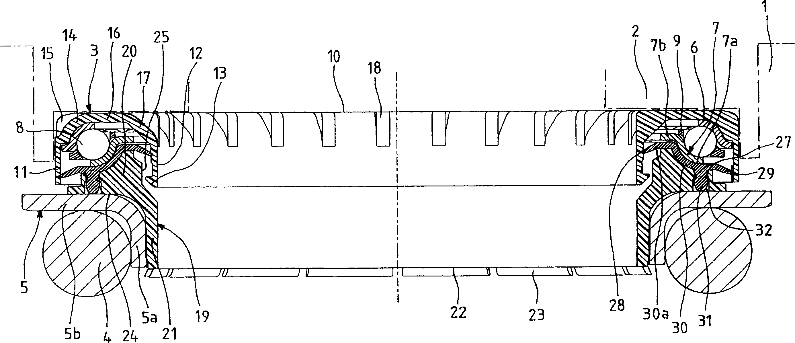
[0043] A shock absorber comprises a cylinder in which a piston can slide, the piston rod being connected by its upper end to an elastic support block 1 supported on and connected to a chassis member constituting a base.

[0044] The elastic support block 1 includes an upper disk 2 and a rubber block. The upper disk 2 is used as a support for the thrust bearing 3. The rubber block is bonded to the surfaces of these three components, and the vibration filter between them is realized. Connection.

[0045] A suspension spring 4 is pressed against a lower disc 5 which is pressed against the thrust bearing 3 .

[0046] The upper disc 2 comprises a downwardly extending cylindrical portion 2a on the opposite side of the base frame and an outwardly extending radial portion 2b. The inner surface of the cylindrical portion 2a and the upper surface of the radial portion 2b are covered with the elastic material used in the elastic support block 1 .

[0047] Obviously, this support supers...


PUM


Abstract

The bearing (3), comprising two rings (6, 7) with rolling bodies (8) between them, a cover (19) in which the first ring (7) is fitted, and a seal (27) that is fixed to the cover and interacts with a fixed or moving surface. The seal has at least one lip lip (28) and is attached to the cover by a series of axial projections (31) on its connecting portion (30). The projections, which penetrate at least partly into one or more cavities (32) in the cover, can be in two concentric rings and made in the shape of rivets.

Description

technical field [0001] The invention relates to the field of suspension thrust bearings, in particular for use in telescopic suspension arms of steered wheels on motor vehicles. [0002] Generally speaking, a suspension thrust bearing includes an upper ring and a lower ring, and ball or roller-shaped rolling elements are arranged between the upper and lower rings. [0003] In particular, the invention relates to a suspension thrust bearing arranged between a bearing block connected to the vehicle body and a bearing block connected to the suspension spring. Background technique [0004] In a known manner, the suspension thrust bearing is arranged in the upper part of the suspension arm, between the lower disk, which also serves as a spring support for the suspension, and the upper part, which is fixed to the body. The spring of the suspension device is installed around the piston rod of the shock absorber, and the end of the piston rod of the shock absorber is connected with...

Claims


Application Information

Patent Timeline
Patent Type & Authority Applications(China)
IPC IPC(8): B60G11/16B60G15/06F16C33/76
CPCB60G2204/418F16C33/761B60G15/068B60G15/063B60G2204/124F16C35/04F16C19/10B60G11/16F16C2326/05
Inventor 让·M·古干伊薇斯-安德烈·利夫莱托布鲁诺·蒙特博尤弗
Owner AB SKF
Why Eureka
Try Eureka