
Manned rice transplanter

A rice transplanter and manned technology, which is applied in the field of manned rice transplanters, can solve the problems such as the inability to set turns, the inability to maintain the grounding state of the buoy, and the inability to quickly switch the grounding state of the buoy, so as to achieve the effect of realizing the operation.

Inactive Publication Date: 2005-08-03
ISEKI & CO LTD
View PDF1 Cites 6 Cited by
  • Summary
  • Abstract
  • Description
  • Claims
  • Application Information

AI Technical Summary

Problems solved by technology

[0004] However, the manned rice transplanter disclosed in the above-mentioned Japanese Patent Application Laid-Open No. 2002-335722 requires additional operations different from the steering operation of the body, so that the rice shoot planting device is tilted forward, and the front part of the flat buoy is grounded. The tilting action of the body takes time, during which the grounding state of the buoy cannot be quickly switched. In addition, when the body turns, in addition to the steering operation of the body, another operation must be performed
If you forget this, you will not be able to maintain proper grounding of the buoys when turning
[0005] In addition, the above invention cannot independently set the control sensitivities of the lift control of the seedling planting device at the time of straight-forward transplanting and turning. Therefore, it is not possible to optimally set the control sensitivity of the seedling planting device according to the transplanting plot regardless of the control sensitivity at the time of planting. control sensitivity

Method used


Image

  • Manned rice transplanter
  • Manned rice transplanter
  • Manned rice transplanter

Examples


Embodiment Construction

[0027] The 8-row planting manned rice transplanter as an embodiment of the present invention will be described in detail according to the accompanying drawings.

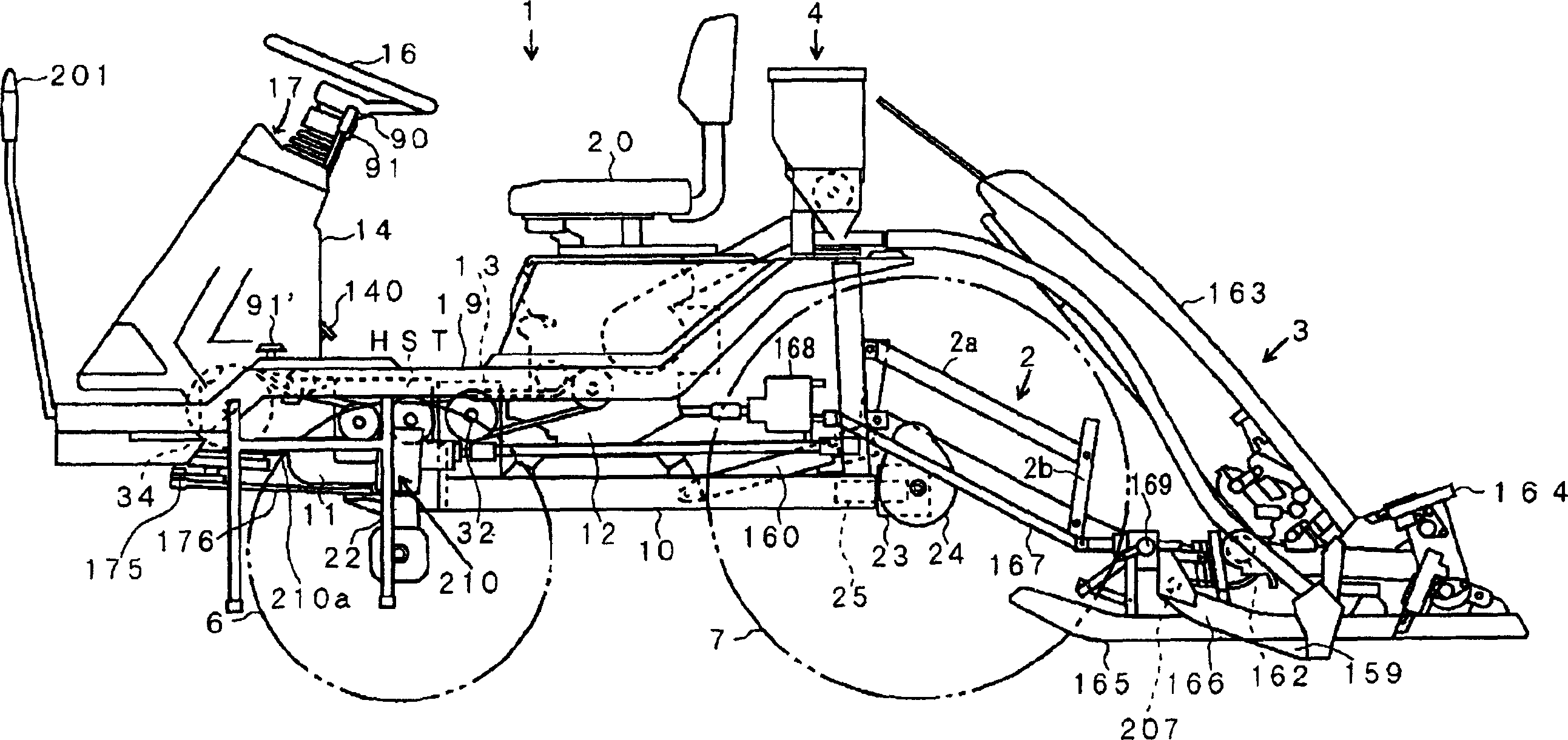
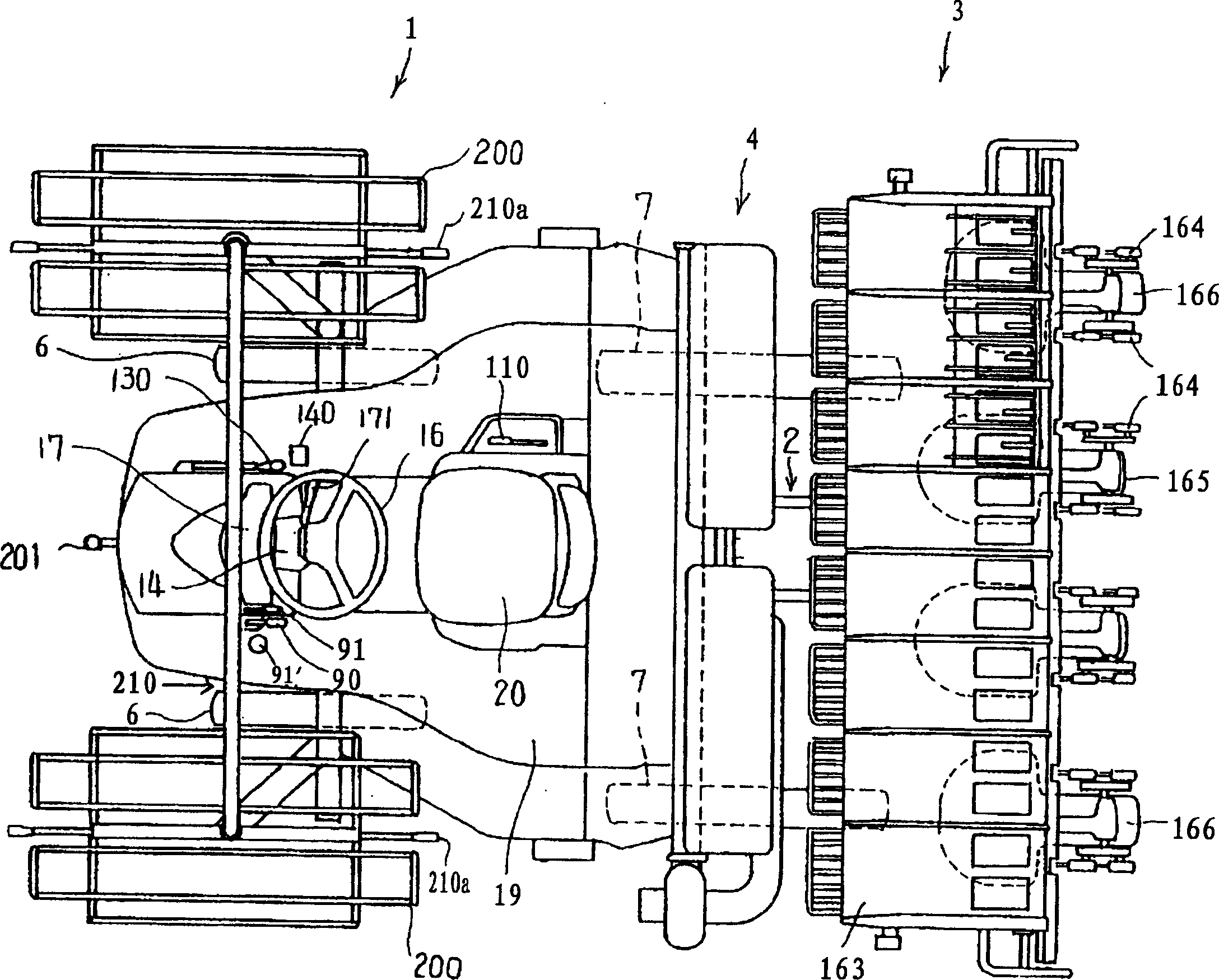
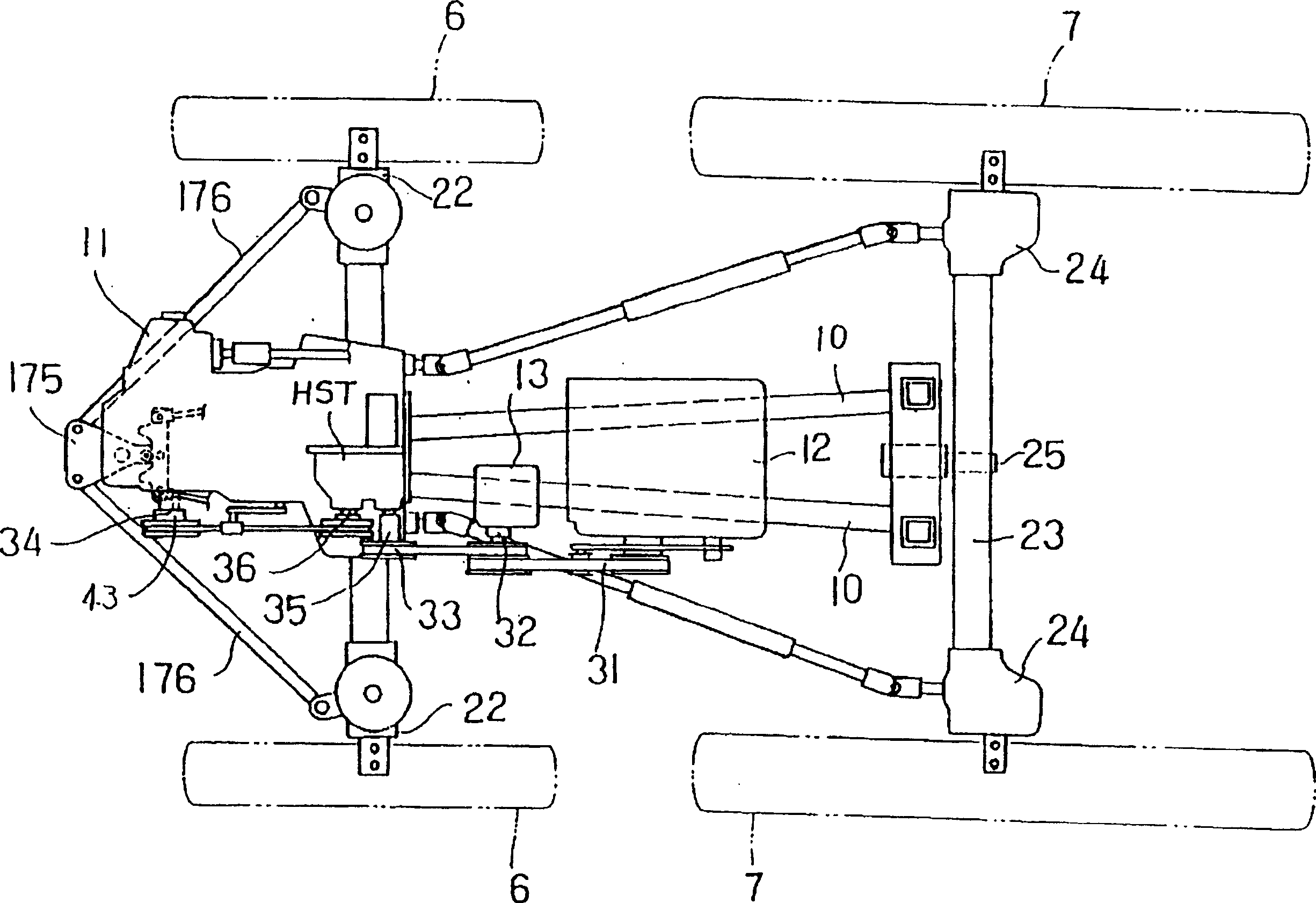
[0028] figure 1 It is an overall side view of the manned rice transplanter of the present invention, figure 2 for the overall floor plan. image 3 to represent figure 1 A schematic plan view of the transmission structure of the walking vehicle of the manned rice transplanter, and Fig. 4 is an expanded sectional view of the gearbox body.

[0029] Such as figure 1 As shown in the side view, the manned rice transplanter uses a lifting link device 2 composed of a horizontal link 2a and a longitudinal link 2b to install a seedling planting device 3 as a working device on a walking vehicle 1. At the same time, A fertilization device 4 is provided, and the whole has the function of carrying manned fertilization and transplanting rice seedlings. The traveling vehicle 1 is a four-wheel drive vehicle having a pair of lef...


PUM


Abstract

The invention provides a sulky rice transplanter having excellent turning properties in distinction from the time of straight advancing and designed to automatically grade a field surface during turning at the side of a levee, or the like. This sulky rice transplanter is equipped with the following: wheels 6 and 7 driven with power from an engine 12, a right and a left side clutches I for individually engaging and disengaging the transmission to the wheels 7 by steering operation of a steering wheel 16, a freely liftable and lowerable seedling planting apparatus 3 performing grading operation during the turning and seedling planting operation when straight advancing and dials 184 and 185 for individually and automatically carrying out operation for grading the field and the seedling planting operation based on lifting and lowering positions of the seedling planting apparatus, the steering wheel steering angle during the turning and the number of revolutions of the wheel on the inside of the turning and individually independently changing the setting of control sensitivity of the lifting and lowering positions of the seedling planting apparatus when the grading operation and the seedling planting operation during the straight advancing are performed. Thereby, the sensitivity is automatically changed over interlockingly with the changeover of the seedling planting operation during the straight advancing operation and the grading operation during the turning operation and both the seedling planting operation and the grading operation can well be carried out. The operation can be optimized.

Description

technical field [0001] The invention relates to a manned rice transplanter. Background technique [0002] As a prior art of this type, as shown in Japanese Patent Application Laid-Open No. 2002-335722, when turning back and turning around at the terminal part of the rice seedling transplanting stroke such as the ground, the rear part of the rice seedling planting device is not rotated as a whole, but the rear part is raised. , A device with excellent turning performance that grounds the front part of the level buoy to level the ground and turn quickly. [0003] Patent Document 1: Japanese Patent Laid-Open No. 2002-335722 [0004] However, the manned rice transplanter disclosed in the above-mentioned Japanese Patent Application Laid-Open No. 2002-335722 requires additional operations different from the steering operation of the body, so that the rice shoot planting device is tilted forward, and the front part of the flat buoy is grounded. The tilting action of the pontoon i...

Claims


Application Information

Patent Timeline
Patent Type & Authority Applications(China)
IPC IPC(8): A01C11/02A01B63/10A01C11/00
CPCG01R1/07342G01R31/2601
Inventor 长井博加藤哲
Owner ISEKI & CO LTD
Learn More