Substrate duster

A technology for dust removal devices and substrates, which are used in cleaning methods using tools, electrical components, and printed circuit manufacturing.

A technology for dust removal devices and substrates, which are used in cleaning methods using tools, electrical components, and printed circuit manufacturing.

CN1652664AInactive Publication Date: 2005-08-10NAGAOKA SEISAKUSHO

Image

  • Substrate duster
  • Substrate duster
  • Substrate duster

Examples


Embodiment Construction

[0042] Hereinafter, embodiments of the present invention will be described with reference to the drawings.

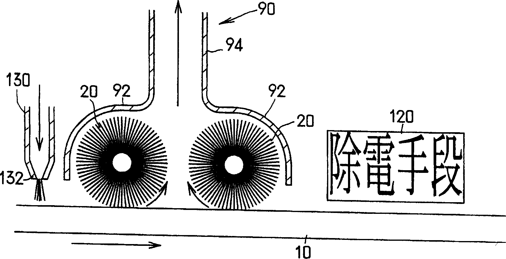
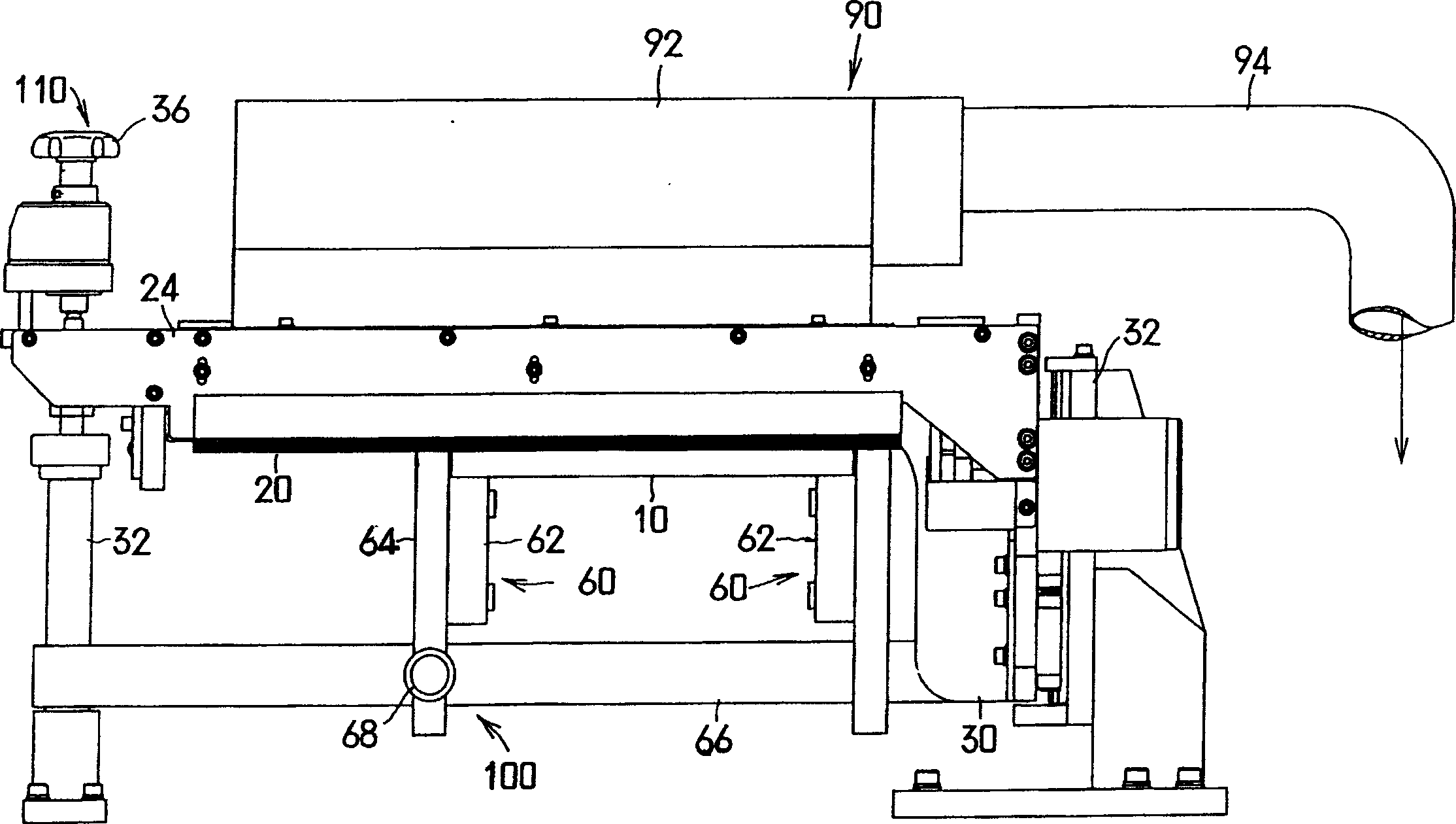
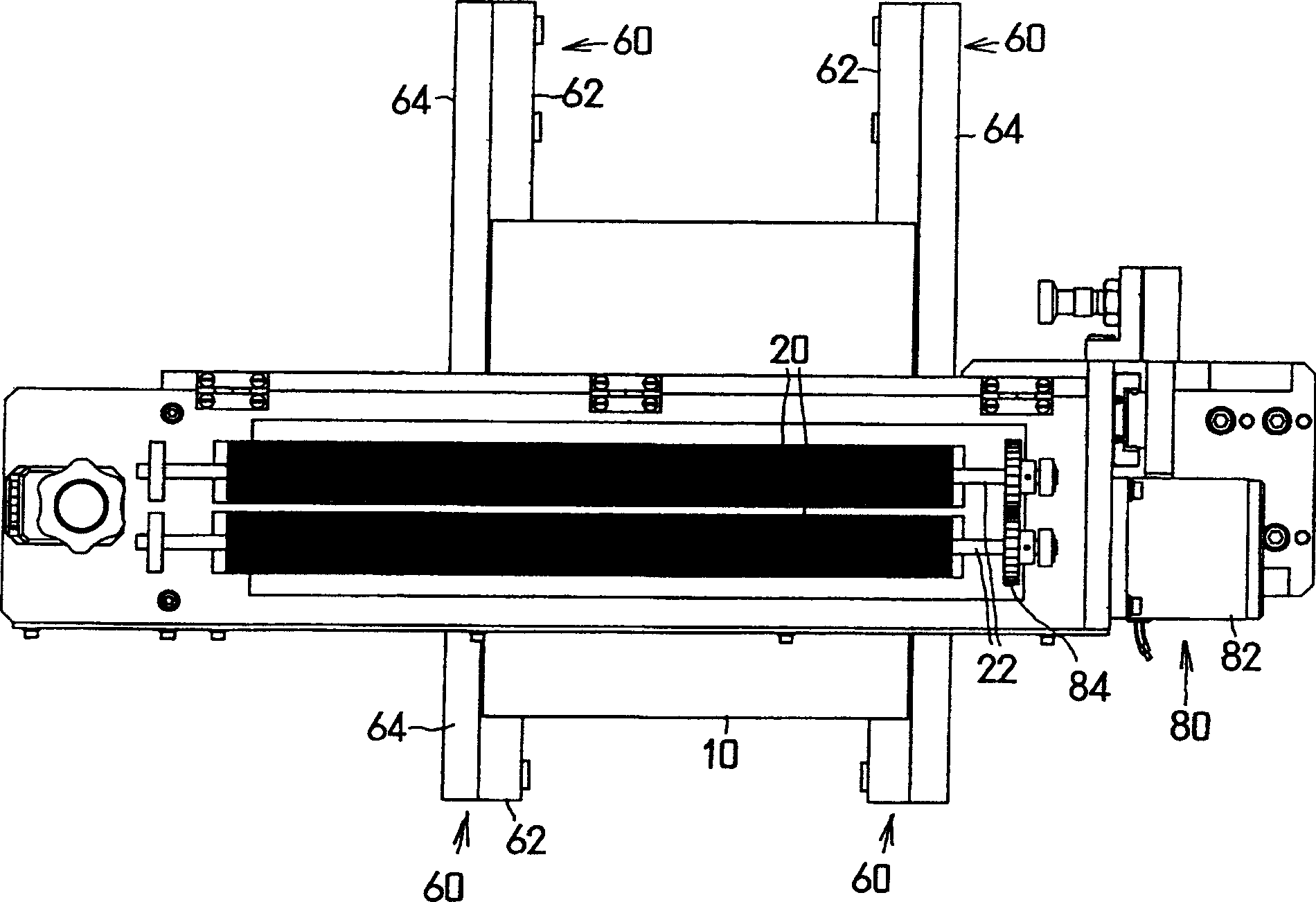
[0043] Figure 1 to Figure 3 A preferred embodiment of the substrate dust removal device of the present invention is shown, figure 1 It is a diagram illustrating its principle structure, figure 2 is its front view, image 3 It is a top view of the state with its dust removal device removed. Next, this substrate dust removal device will be described.

[0044] In this substrate dedusting device, such as figure 2 with image 3 As shown, a conveyor 60 for loading and transporting substrates 10 is included. The conveyor 60 is configured such that a pair of left and right endless endless belts 62 are synchronously circulated inside a pair of conveyor frames 64 in the same direction and at the same speed. At the same time, the substrate 10 mounted on the entire pair of left and right endless belts 62 is conveyed at the same speed as the endless belts 62 along the cir...


PUM


Abstract

To provide a substrate dust removal apparatus capable of sucking and removing approximately whole of dust scraped from a surface of the substrate by a rotating rotation brush roller. The two rotation brush rollers 20 rotating toward reverse directions each other are press-contacted with a surface of a substrate 10 placed and conveyed on a conveyor directed toward a direction crossing the substrate 10. Then, the dust deposited on the surface of the substrate 10 is scraped off from the surface of the substrate by the rotating rotation brush roller 20, is floated between the two rotation brush roller 20 and is deposited on the two rotation brush roller 20. Then, the dust is sucked to the inner side of a dust removal means 90 while passing through a dust-collection port 92 of the dust removal means continuously covering an upper periphery of the two rotation brush roller 20 and is discharged.

Description

technical field [0001] The present invention relates to a substrate dust removal device for removing dust adhering to substrates such as printed wiring boards. Background technique [0002] In the substrate such as the above-mentioned printed wiring board, when dust such as solder shavings or dust or dust adheres to the surface of the substrate, the resistance value of the place where the dust adheres will decrease, which may impair the function of the substrate. Danger. Such a decrease in resistance value due to the adhesion of dust is fatal to the state of recent substrates for semiconductor devices that operate with weak electric power. [0003] Therefore, in an assembly operation of such a substrate for a semiconductor device, etc., a step of removing dust on the substrate is generally added. [0004] As a dust removal device used in the dust removal step of such a substrate, there is a dust removal device described in JP-A-2003-334499. [0005] In the method of remov...

Claims


Application Information

Patent Timeline
10 Aug 2005
Publication
CN1652664A
IPC
B08B5/04; B08B1/20; B08B5/02; H05K3/00
Inventors
池田茂树