Locks for doors

A technology for a lock device and a door, which is used in construction locks, non-mechanical transmission-operated locks, construction, etc., and can solve problems such as inability to open, inability to unlock, and difficulty in releasing the abutment between the locking plate 53 and the stop arm 55, etc. , to achieve the effect of real unlocking and smooth unlocking

Inactive Publication Date: 2005-08-31
ALPHA
View PDF0 Cites 8 Cited by
  • Summary
  • Abstract
  • Description
  • Claims
  • Application Information

AI Technical Summary

Problems solved by technology

[0008] However, in the above-mentioned prior door lock device 51, since the user of the cabinet puts large goods into the cabinet 69, the goods are locked in a state in which the door 72 is pushed from the inside of the cabinet to the opening direction (a state of applying back pressure). When locked, it will be as Figure 10 As shown, the hook 52 pushes the locking plate 53 along the unlocking direction (the direction of clockwise rotation), so that the locking plate 53 is tightly abutted against the stop arm 55, thereby preventing the rotation of the locking plate 53 and making the door 72 become a problem that cannot be opened
[0009] At this time, although the cabinet user shakes the door 72 back and forth and tries to open it (when the door 72 is pushed inwardly against the back pressure, the hook 52 rotates the locking plate 53 a little to the unlocking direction, and the locking plate is released. 53 and the stop arm 55), but since the unlocking operation force is transmitted to the stop arm 55 through the plunger 66 and the drive rod 56, the click between the plunger 66 and the drive rod 56 and the stop arm 55 There is a time lag in the driving of the stop arm 55 due to rattling, etc., so that the contact between the lock plate 53 and the stop arm 55 is difficult to be released, and there is a problem that the lock cannot be unlocked smoothly.
[0010] And, since the above-mentioned antitheft performance of the previous door lock device 51 depends on the strength of the lock plate 53 clamping (embracing) the hook 52 and the strength of the stop arm 55 fixing the hook 52 at the locked position, The anti-theft performance (making the strength not to be unlocked) is limited, and there will be such a problem, that is, when the thief slams the door of the cabinet to the opening direction with a tool such as a sled bar, the hook 52 of the door will forcibly make the door open. The locking plate 53 rotates to the unlocking direction to open the door

Method used


Image

  • Locks for doors
  • Locks for doors
  • Locks for doors

Examples


no. 1 Embodiment approach

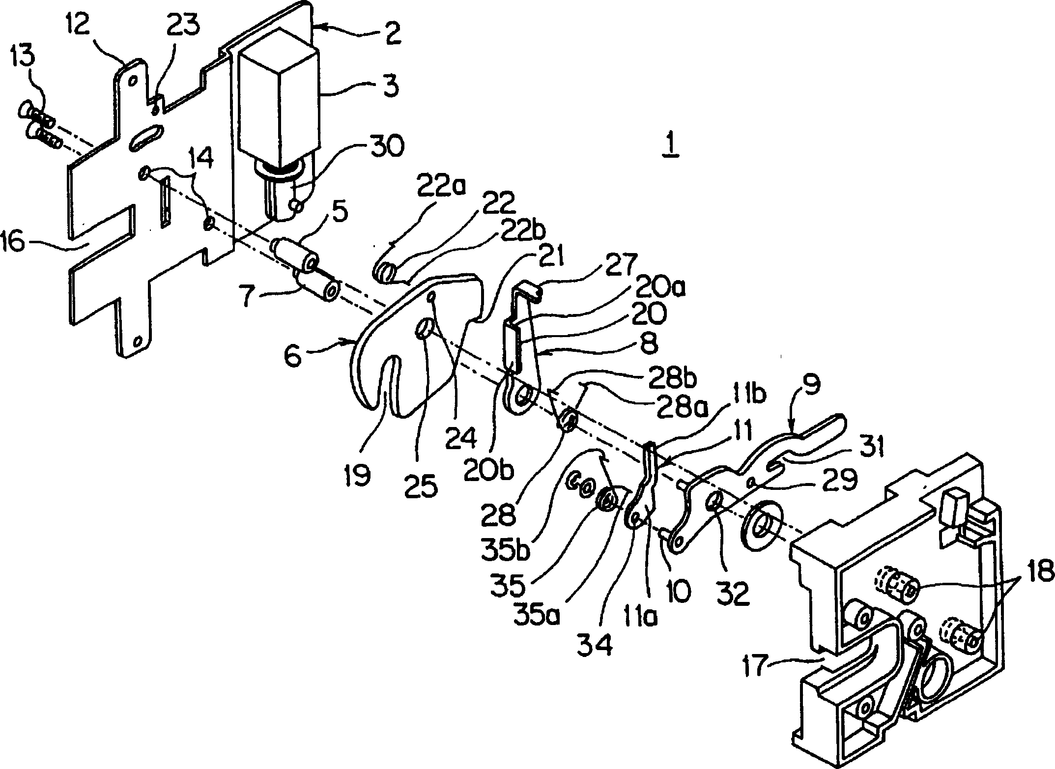
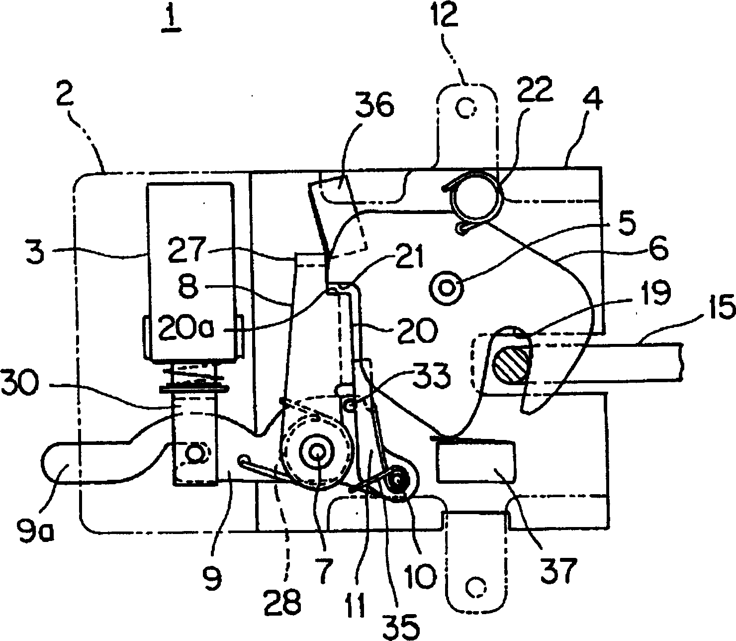
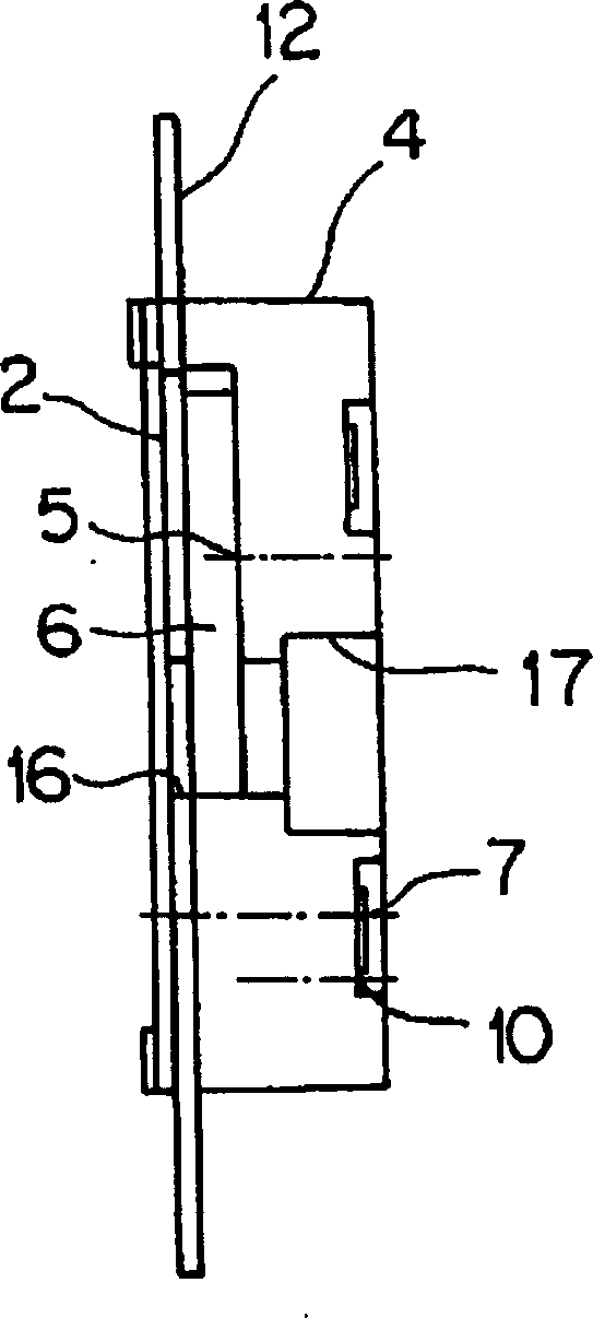
[0037] Figure 1 to Figure 6 The door lock device according to the first embodiment of the present invention is shown.

[0038] Such as figure 1 As shown, the door lock device 1 is provided with: an electric solenoid (drive mechanism) 3 fixed on a base plate 2; The locking plate 6 on the shaft 5; the stop arm 8 rotatably supported on the second fulcrum 7; Drive lever 9; freely rotatably supported on the shaft portion 10 on the front end side of the drive lever 9, and springs the stop arm 8 to the unlocking direction, that is, to the direction where the abutment between the locking plate 6 and the stop arm 8 is released. direction of the detent release arm 11.

[0039] The structure of the base plate 2 or the case 4, the solenoid 3, the lock plate 6, and the stopper arm 8 is the same as the previous structure.

[0040] That is, the base plate 2 has: screwed on the lock (refer to Figure 9 ) the fixing portion 12 on the inner wall; the hole portion 14 for fixing each horiz...

no. 2 Embodiment

[0076] Figure 7 ~ Figure 9 It is a door lock device (anti-theft lock device) showing a second embodiment of the present invention.

[0077] Such as Figure 7 As shown, the anti-theft lock device 101 is provided with: an electric solenoid (drive mechanism) 103 fixed on a base plate (mounting plate) 102; The lock plate 106 rotatably supported by the fulcrum 105; the stopper arm 108 rotatably supported by the second fulcrum 107; the action of the solenoid 103 rotatably supported by the second fulcrum 107; The drive lever 109 that can rotate up and down is characterized in that a protrusion (convex portion) 114 for preventing rotation (unlocking) is provided on the lock plate 106, and a hole (concave portion) 114 for engaging with the protrusion 114 is provided on the base plate 102. )118.

[0078] The base plate 102 or locking plate 106, the stopper arm 108, and the driving rod 109 are all formed of metal materials. The structures and functions of the solenoid 103, the stop ...


PUM


Abstract

PROBLEM TO BE SOLVED: To surely prevent unlocking when someone tries to force a door of a locker open.

Description

technical field [0001] The present invention relates to a lock device for a door, which is a device for locking and unlocking a cabinet with a rotary door, such as a paid automatic storage box or a door-to-door cabinet; In particular, it relates to a door lock device that can be reliably unlocked even when a large cargo is placed in the cabinet and there is a back pressure on the door, and the act of forcibly unlocking the sled door enhances theft prevention High-performance door lock device. Background technique [0002] Figure 10 ~ Figure 12 Represents one form of a conventional door lock device (for example, refer to Japanese Patent No. 3443212, pages 3-4, Figure 7 ~Figure 8, Figure 11 ). [0003] The structure of this door lock device 51 is to be provided with: hang the hook 52 on the door side and lock the rotary locking plate 53; the locking plate 53 is bounced to the winding spring 54 of the unlocking direction; the locking plate 53 is prevented from unlocking. ...

Claims


Application Information

Patent Timeline
Patent Type & Authority Applications(China)
IPC IPC(8): E05B47/06E05B63/00
Inventor 森下吉巳
Owner ALPHA
Why Eureka
Try Eureka