Improved electric power drawer cabinet

A drawer cabinet and an improved technology, which is applied to pull-out switch cabinets, electrical components, switch devices, etc., can solve the problems of unstable lock, low maintenance efficiency, and poor lock quality of the drawer cabinet, and improve the maintenance efficiency. The effect of saving input costs and increasing the number of lock-ups

Active Publication Date: 2017-05-10
JIANGSU HUAFU ELECTRIC POWER TECH CO LTD
View PDF3 Cites 2 Cited by
  • Summary
  • Abstract
  • Description
  • Claims
  • Application Information

AI Technical Summary

Problems solved by technology

[0003] The locking of existing drawer cabinets is often to set a lock at the front end of the drawer cabinet for locking, and each drawer cabinet is equipped with a lock. Opening for inspection is very inconvenient for inspection and the inspection efficiency is low. Moreover, due to safety fa

Method used


Image

  • Improved electric power drawer cabinet
  • Improved electric power drawer cabinet
  • Improved electric power drawer cabinet

Examples


Embodiment Construction

[0018] The preferred embodiments of the present invention will be described in detail below in conjunction with the accompanying drawings, so that the advantages and features of the present invention can be more easily understood by those skilled in the art, so as to define the protection scope of the present invention more clearly.

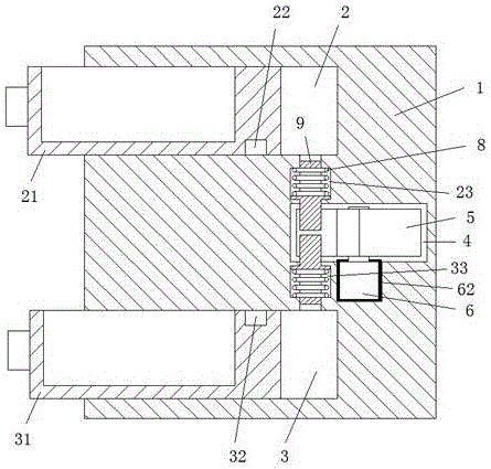
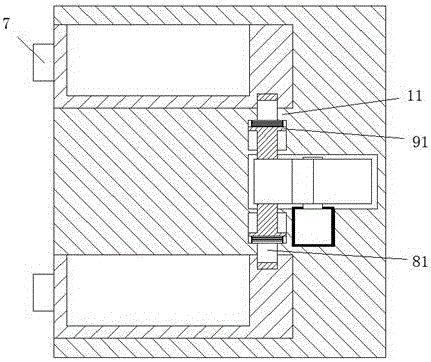
[0019] refer to Figure 1-5 As shown, an improved electric drawer cabinet of the present invention includes a base 1, an upper cabinet cavity 2 and a lower cabinet cavity 3 arranged in the base 1, and the upper cabinet cavity 2 and the lower cabinet cavity 3 are respectively slidable left and right. The upper cabinet body 21 and the lower cabinet body 31 in the lower cabinet cavity 3, and the upper lock groove 22 arranged on the lower right side of the upper cabinet body 21, and the lower lock groove 32 arranged on the upper right side of the lower cabinet body 31, the base An upper sliding cavity 23 and a lower sliding cavity 33 are also provide...


PUM


Abstract

The invention discloses an improved electric power drawer cabinet. The improved electric power drawer cabinet includes a base (1), an upper cabinet cavity (2) and a lower cabinet cavity (3) arranged in the base (1), an upper cabinet body (21) and a lower cabinet body (31) respectively arranged in the upper cabinet cavity (2) and the lower cabinet cavity (3) in a manner of sliding left and right, an upper lock groove (22) arranged in the lower side of the right side of the upper cabinet body (21) and a lower lock groove (32) arranged in the upper side of the right side of the lower cabinet body (31). The base (1) is also therein provided with an upper slide cavity (23) and a lower slide cavity (33). A drive assembly accommodating cavity (4) is arranged between the upper slide cavity (23) and the lower slide cavity (33) in a communicating manner. The upper slide cavity (23) is communicated with the right side of the upper cabinet cavity (2). The lower slide cavity (33) is communicated with the right side of the lower cabinet cavity (3). Locking parts that are symmetric and capable of sliding up and down are respectively arranged in the upper slide cavity (23) and the lower slide cavity (33).

Description

technical field [0001] The invention relates to the field of electric power, in particular to an improved electric drawer. Background technique [0002] Drawer-type electrical control cabinets are widely used, and they are often used in the field of power control. There are usually various electrical components in the drawer-type electrical control cabinet. Therefore, locking the drawer under normal use is an important measure to ensure safe operation. [0003] The locking of existing drawer cabinets is often to set a lock at the front end of the drawer cabinet for locking, and each drawer cabinet is equipped with a lock. It is very inconvenient to open for inspection, and the inspection efficiency is low. Moreover, due to safety factors, it is necessary to ensure that there is no rigid collision during the unlocking process, so as not to cause heat or even sparks. Moreover, the locks used in the existing drawer cabinets are of poor quality and are very easy to damage. Thi...

Claims


Application Information

Patent Timeline
IPC IPC(8): H02B11/173E05B63/14E05B47/02E05B65/462
CPCE05B47/0012E05B47/026E05B63/146E05B65/462H02B11/173
Inventor 邓聪迪
Owner JIANGSU HUAFU ELECTRIC POWER TECH CO LTD
Why Eureka
Try Eureka