Device for connecting building boards, especially floor panels

A technology for building panels and floors, which can be used in construction, sheet connection, connection components, etc., and can solve problems such as floor damage

Inactive Publication Date: 2006-06-28
KRONOTEC
View PDF1 Cites 14 Cited by
  • Summary
  • Abstract
  • Description
  • Claims
  • Application Information

AI Technical Summary

Problems solved by technology

For laminated panels, the core is made of wood, in which case it will expand, causing damage to the floor

Method used


Image

  • Device for connecting building boards, especially floor panels
  • Device for connecting building boards, especially floor panels
  • Device for connecting building boards, especially floor panels

Examples


Embodiment Construction

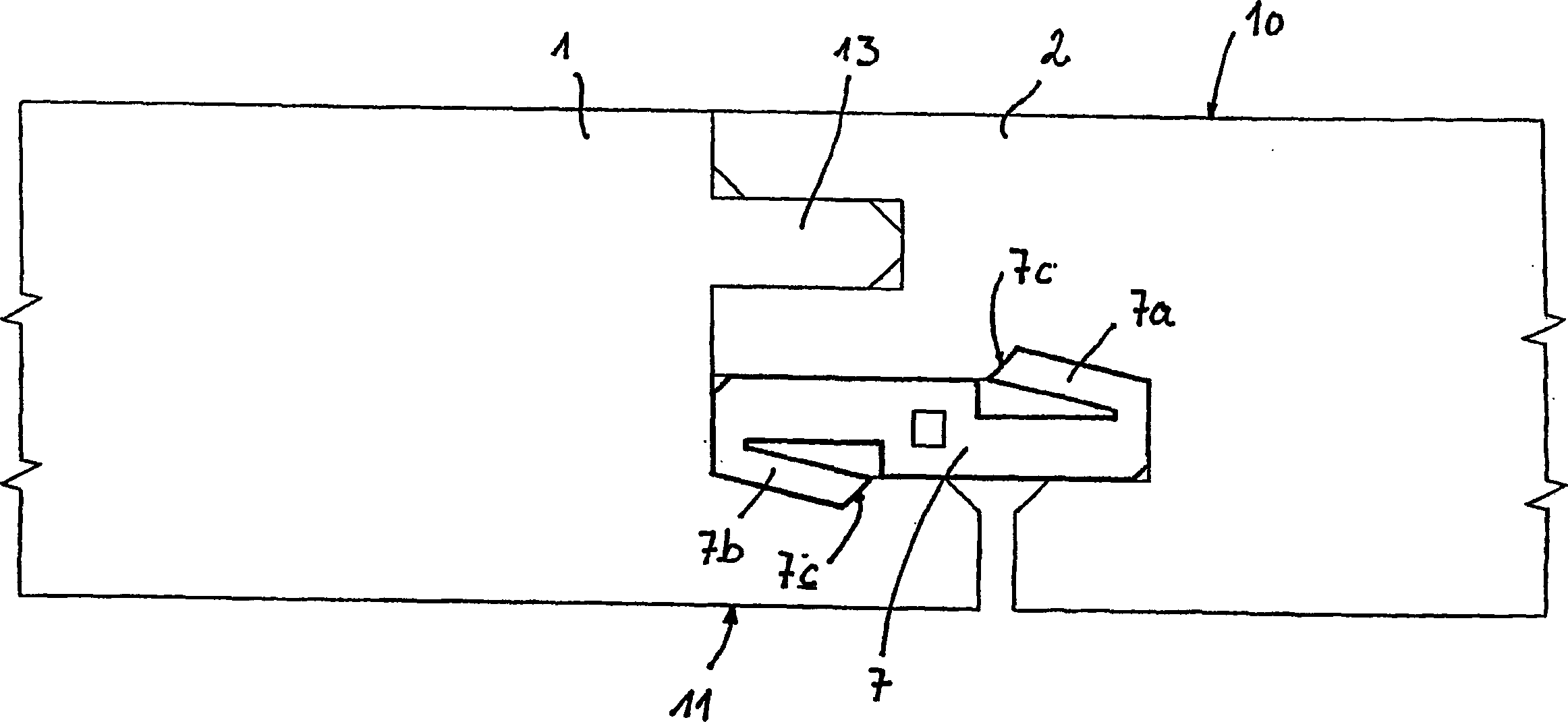
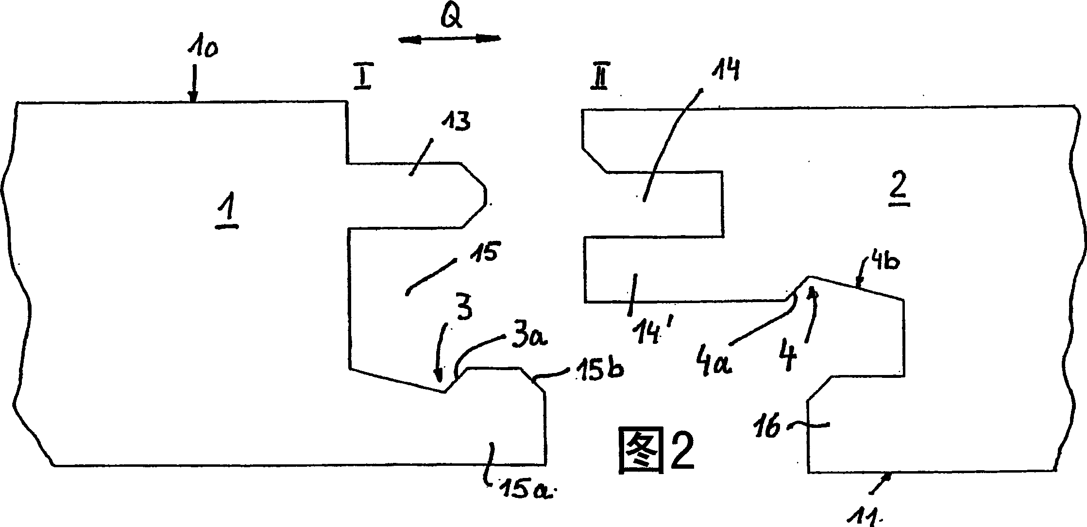
[0038] The laminated panels 1, 2 comprise a core made of wood, preferably MDF or HDF. It has a tongue 13 and a groove 14 on its sides I, II. Below the bottom lip 14' of the groove 14, the material of the plate 2 is cut down to the bottom side 11. Below the tongue 13, on the opposite side I, a groove 15 with a bottom lip 15a is formed. On its side facing the tongue 13 , the bottom lip 15 a has a groove 3 with an obliquely running edge 3 a. On the opposite side II, the underside of the bottom lip 14a likewise has a groove 4 which has an obliquely running edge 4a.

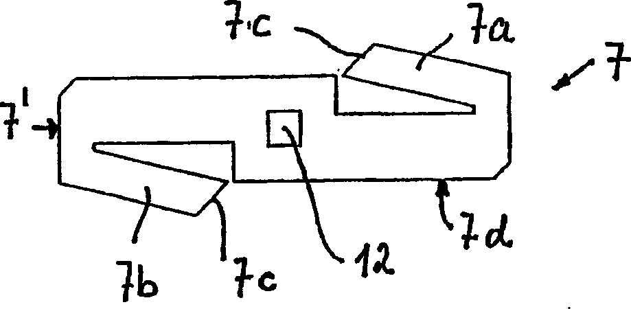
[0039] like image 3 As shown, the locking insert 7 has two oppositely acting elastic lips 7a, 7b, both of which have obliquely extending ends 7c. The insert 7 is designed symmetrically with respect to the two main axes. There is a hole 12 in the center.

[0040] To connect two boards 1, 2, the elastic lip 7a of the insert 7 is first inserted into the slot 4, with the end 7c abutting against the inclined extendi...


PUM


Abstract

The device for the connecting and locking of especially floor panels (1,2) with a core made from a derived timber product has an insert (7) for fitting in respective slots in the side edges of the panels. The insert has at least one spring lip (7a) orientated towards the upper side (10) or lower side (11) of the panel, and may have two oppositely orientated lips. The spring lips each have a point (7c) extending at an angle to the upper of lower side and interacting with an angled edge for locking purposes.

Description

technical field [0001] The invention relates to a device for connecting and locking building panels comprising a top side and a bottom side, in particular a floor with a core made of wood, and having grooves on at least two of its opposite sides, so that The device also includes inserts for locking purposes, said inserts being insertable into one of the side slots, the plates being connected by a substantially horizontal movement. Background technique [0002] Such devices are known, for example, from DE10034409. On the insert, a plurality of barbs are formed mirror-symmetrically about its center. The barbs point toward each other. To make a connection, insert the card into one slot, then connect the other board's slot to the card. The core of the insert corresponds to the height of the groove. The barbs protrude beyond the core. The formation of the lock is indeterminate, where the barbs are pressed together in the grooves. In order to prevent the interconnected plate...

Claims


Application Information

Patent Timeline
Patent Type & Authority Applications(China)
IPC IPC(8): E04F15/04E04B1/61E04F13/08E04F13/10E04F15/08F16B5/00F16B12/24
CPCE04B1/6129E04B1/615E04F13/10E04F15/04E04F2201/0107E04F2201/0115E04F2201/023E04F2201/025E04F2201/0523F16B5/002E04F15/02
Inventor 托马斯·格拉芬奥尔马蒂亚斯·莱瓦尔克
Owner KRONOTEC
Why Eureka
Try Eureka