Fuel tank cover module

A fuel tank cap and module technology, which is applied in the application of connecting components, vehicle parts, locks, etc., can solve the problems of large space and large workload, and achieve the effect of saving space.

Inactive Publication Date: 2008-07-23
GM GLOBAL TECH OPERATIONS LLC
View PDF1 Cites 14 Cited by
  • Summary
  • Abstract
  • Description
  • Claims
  • Application Information

AI Technical Summary

Problems solved by technology

The disadvantage of this known construction is that it requires a lot of work in the final assembly, since the servomotor and the locking lever must be assembled separately from the actual tank cove

Method used


Image

  • Fuel tank cover module
  • Fuel tank cover module

Examples


Embodiment Construction

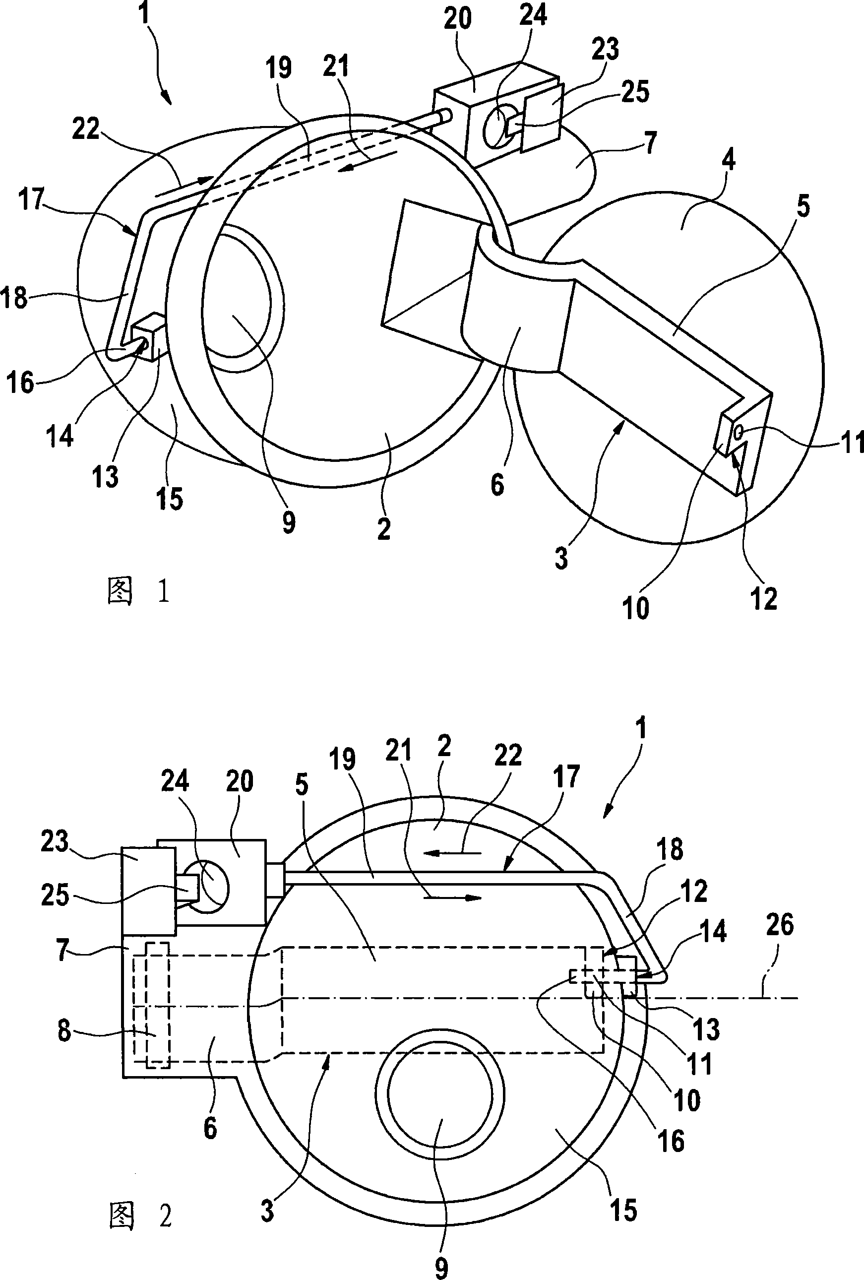
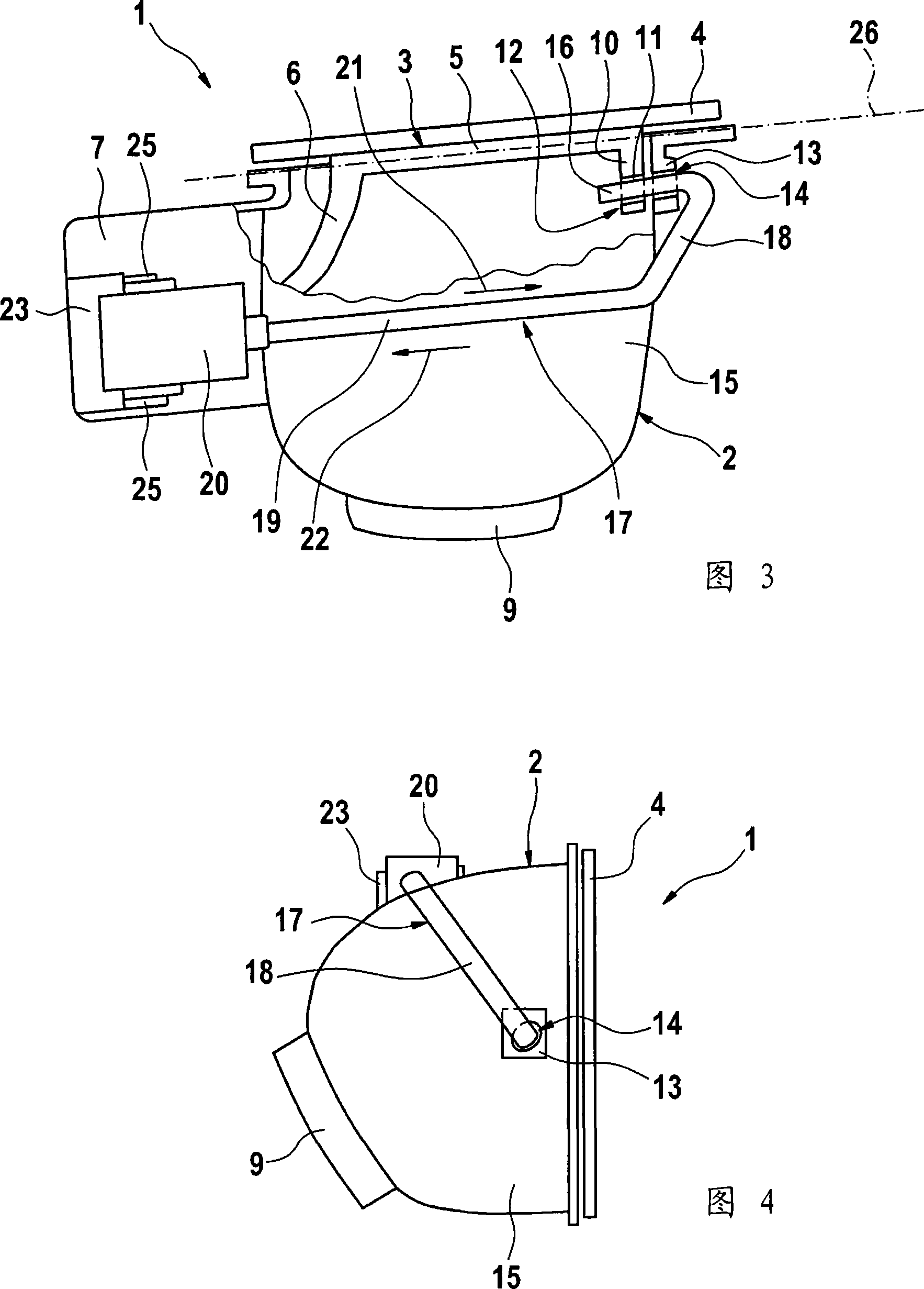
[0021] FIG. 1 shows a tank cover module 1, which comprises a module body 2 and a hinged arm 3 pivotally mounted on the module body 2, on which a fuel tank cover 4 is fastened.

[0022] The articulated arm 3 includes a longitudinal section 5 designed to install the fuel tank cover 4 and an arc section 6 connected thereto. The arc section 6 extends into the expansion shell 7 formed on the side of the module body 2 and can rotate around the axis of rotation. 8 (FIG. 2) is rotatably supported in the expansion housing.

[0023] Hole 9 is formed in the rear area of ​​module body 2, and it is used for installing the oil tank filler connection that is not shown in the figure.

[0024] In the region of the free end of the articulated arm 3 is formed a projection 10 with a hole 11 which together forms a locking piece 12 .

[0025] A guide 13 with a guide hole 14 is arranged on the module body 2 substantially opposite the extension housing 7, the guide hole 14 passing through the wall 1...


PUM


Abstract

The flap module (1), covering the motor vehicle fuel filler cap, has a trough body (2) with a hinge arm (3) for the tank flap (4). The flap swings on an axis (8) at the body at one end, with a locking section (12) at the other end. A setting motor or electromagnet, as a flap control (20), is at the outer side of the body at the swing axis, to grip the locking bolt (17).

Description

technical field [0001] The invention relates to a fuel tank cover module for installation in a car, comprising a module body and a hinged arm fixed on the module body and designed for mounting the fuel tank cover, the hinge arm can be rotatable around a rotary shaft Installed on the module body and at its end facing away from the rotary shaft, there is a lock block, and includes a lock piece, which can be controlled between the locked position and the released position by the controller in order to lock and unlock the fuel tank cap. Switching between, in the locked position the lock is inserted into the lock block, and in the release position the lock is not inserted into the lock block. Background technique [0002] A tank cover module of this type is known, for example, from EP 0736406 A1. In such a fuel tank cover module, the controller, which is designed as a servomotor for locking the fuel tank, is designed independently of the fuel tank cover module and is attached to...

Claims


Application Information

Patent Timeline
IPC IPC(8): B62D25/24E05B65/18
CPCE05B2047/0016B60K2015/0584E05B47/026B60K15/05B60K2015/0561B60K2015/0553E05B47/0012B60K15/04E05B83/34B60K2015/0576Y10T292/1089
Inventor 拉斯·莱德勒克里斯琴·曾特纳
Owner GM GLOBAL TECH OPERATIONS LLC
Why Eureka
Try Eureka