Cover top sealing plate

A technology of sealing plate and roof, which is applied in the direction of vehicle safety arrangement, superstructure, pedestrian/occupant safety arrangement, etc.

Inactive Publication Date: 2005-10-12
日本塑料株式会社
View PDF2 Cites 16 Cited by
  • Summary
  • Abstract
  • Description
  • Claims
  • Application Information

AI Technical Summary

Problems solved by technology

In this document, there is no teaching or suggestion about deformation or breakage of the clamping part due to the absorption of impact force

Method used


Image

  • Cover top sealing plate
  • Cover top sealing plate
  • Cover top sealing plate

Examples


Embodiment Construction

[0022] The preferred embodiments of the present invention will be described in detail below in conjunction with the accompanying drawings. In the description and claims of the present invention, directions such as front, rear, left and right are relative to the direction of motion of the car, and directions such as transverse, longitudinal, up, down, top and bottom are relative to the direction of the car. Orientation in normal placement.

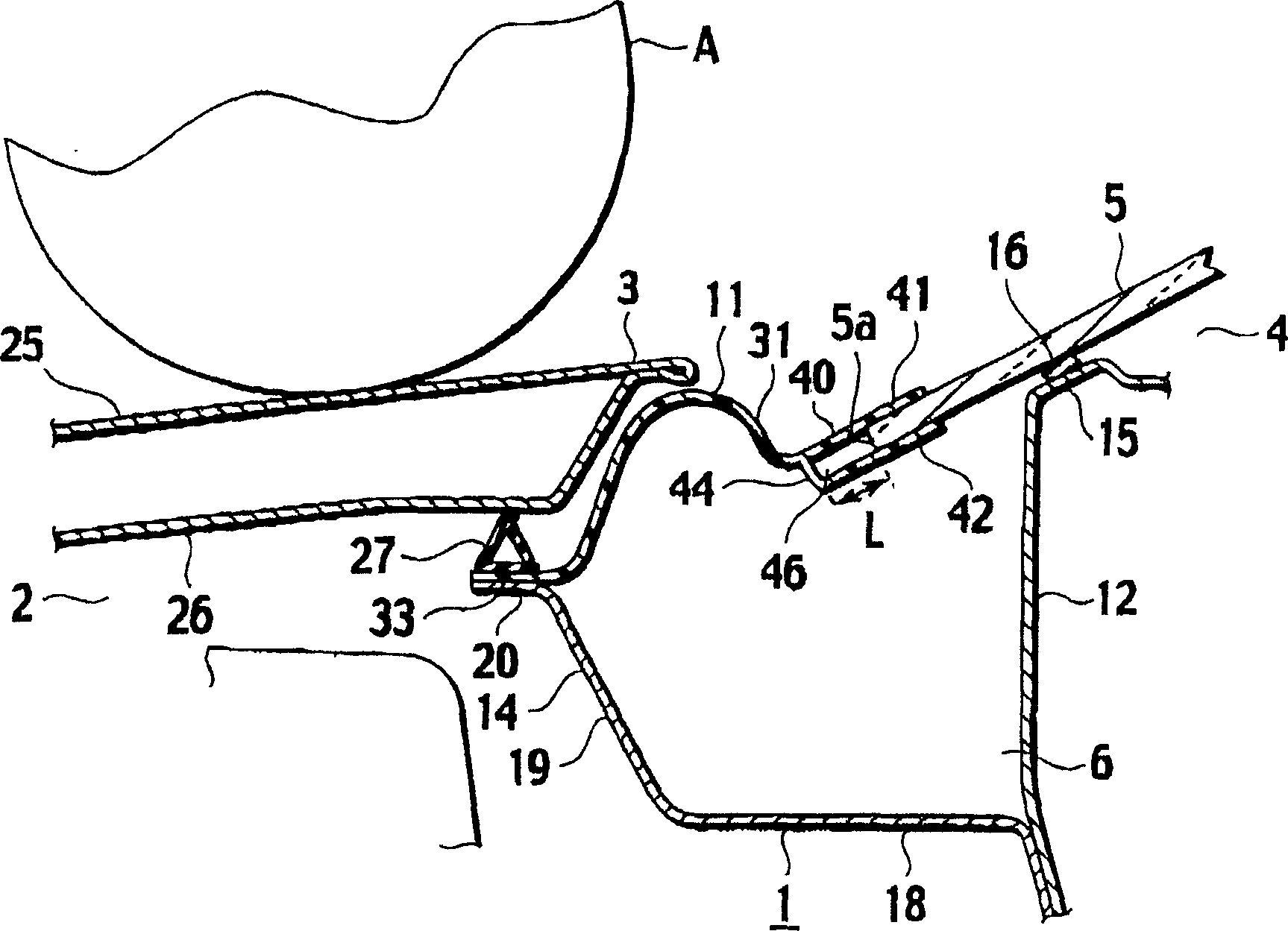
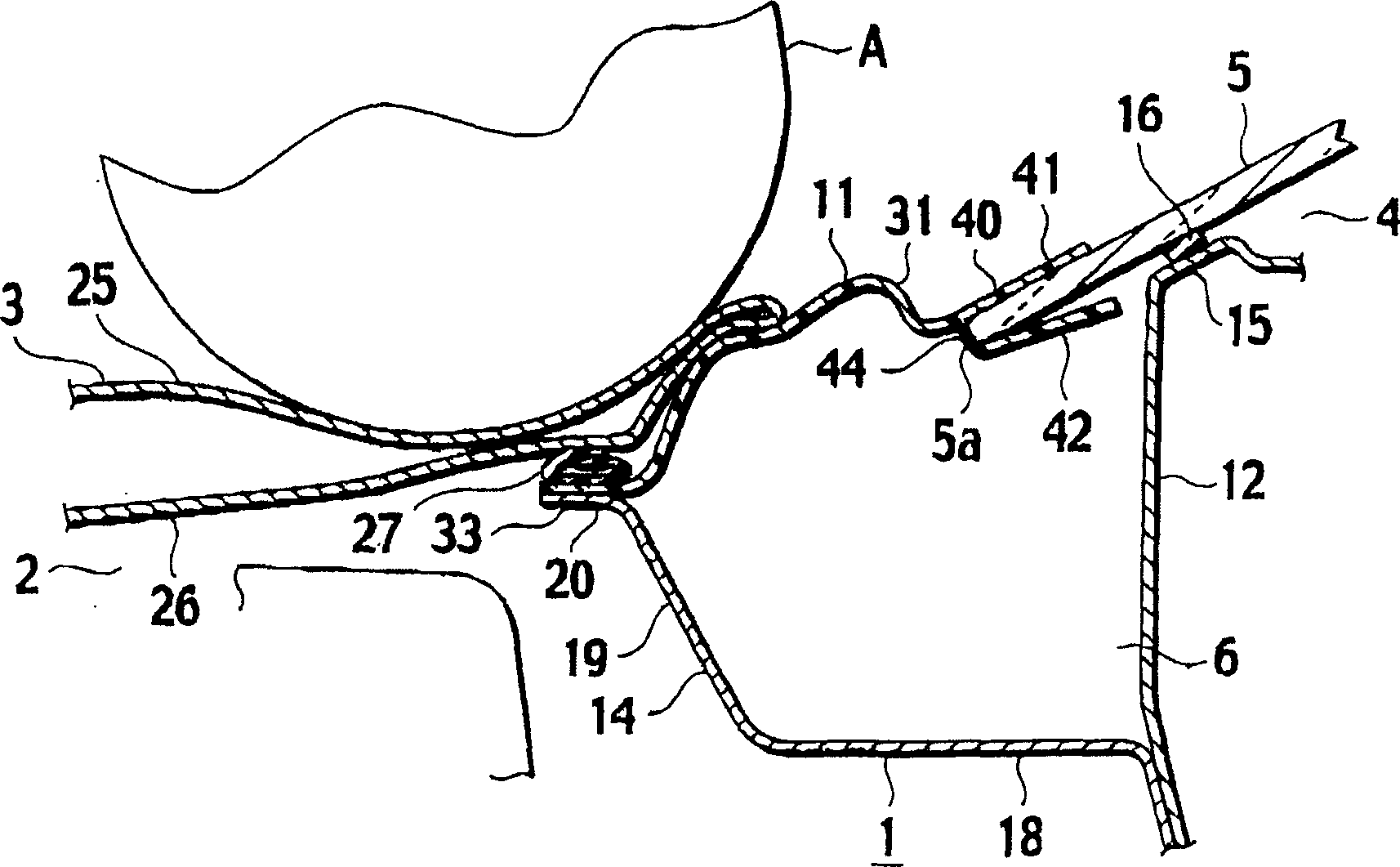
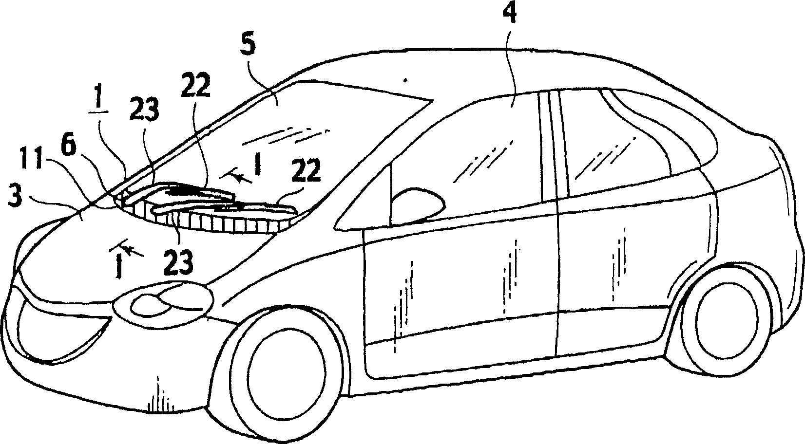
[0023] Below, combined with Figure 1A , 1B and 2 illustrate the first embodiment of the present invention. The motor vehicle 1 is provided with a bonnet 3 and a windshield 5 in front of the driver's cab 4 , wherein the bonnet 3 serves as a counterpart to the hood cover for covering the engine compartment 2 . The ventilation slot 6 is located below the partition between the windshield 5 and the bonnet 3 . The hood sealing plate 11 covers the ventilation slot 6 and the separation area. Such as Figure 1A As shown, the ventilation slot 6, ...


PUM


Abstract

A cowl-top cover for a vehicle having a bonnet hood, a windshield and a well disposed therebetween, is provided with a fixation portion fixed to a body panel of the vehicle on a side of the bonnet hood; an engaging portion including a bottom, the engaging portion being configured to conceal and slidably pinch an end portion of the windshield so that a space portion is defined by the end portion and the bottom; and a main body portion linking the fixation portion with the engaging portion and covering the well, the main body being configured to be deformed by an applied impact force and allow sliding movement of the engaging portion in a direction where the bottom moves toward the end portion of the windshield.

Description

technical field [0001] The present invention relates to a hood cover for covering a ventilation slot between the windshield and the hood of a motor vehicle. Background technique [0002] In a general automobile, a well is provided between a windshield and a hood and is covered with a cowl-top cover. [0003] Japanese Patent Application No. 2002-46649 discloses such a roof sealing plate technology, wherein the roof sealing plate has a closed cross-sectional structure. When the windshield is subjected to an impact force, the closed cross-sectional structure deforms and some of its joints move in position to absorb the impact force. According to this prior art, since the bottom end of the windshield is easily exposed to the outside in case of deformation of the hood closure, the hood closure needs to be adhered to the bottom end of the windshield using a special adhesive. Any teaching or suggestion that the impact force may cause the adhesive part to deform or break and absor...

Claims


Application Information

Patent Timeline
Patent Type & Authority Applications(China)
IPC IPC(8): B62D25/08B62D25/10
CPCB62D25/105B60R21/34B60R2021/343B62D25/081
Inventor 酒井一浩仓田武则石川晃弘小山求松山和夫
Owner 日本塑料株式会社
Why Eureka
Try Eureka