Fluid bed apparatus module and method of changing a first module for a second module in a fluid bed apparatus

A fluidized bed and fluidized gas technology, applied in chemical instruments and methods, hearth furnaces, chemical/physical processes, etc., can solve problems such as labor-intensive and troublesome operation

Active Publication Date: 2007-12-05
科里特股份有限公司
View PDF6 Cites 5 Cited by
  • Summary
  • Abstract
  • Description
  • Claims
  • Application Information

AI Technical Summary

Problems solved by technology

However, handling of different batches is cumbersome and labor-intensive, as the c

Method used


Image

  • Fluid bed apparatus module and method of changing a first module for a second module in a fluid bed apparatus
  • Fluid bed apparatus module and method of changing a first module for a second module in a fluid bed apparatus
  • Fluid bed apparatus module and method of changing a first module for a second module in a fluid bed apparatus

Examples


Embodiment Construction

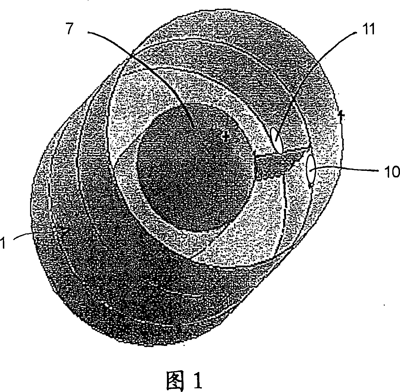
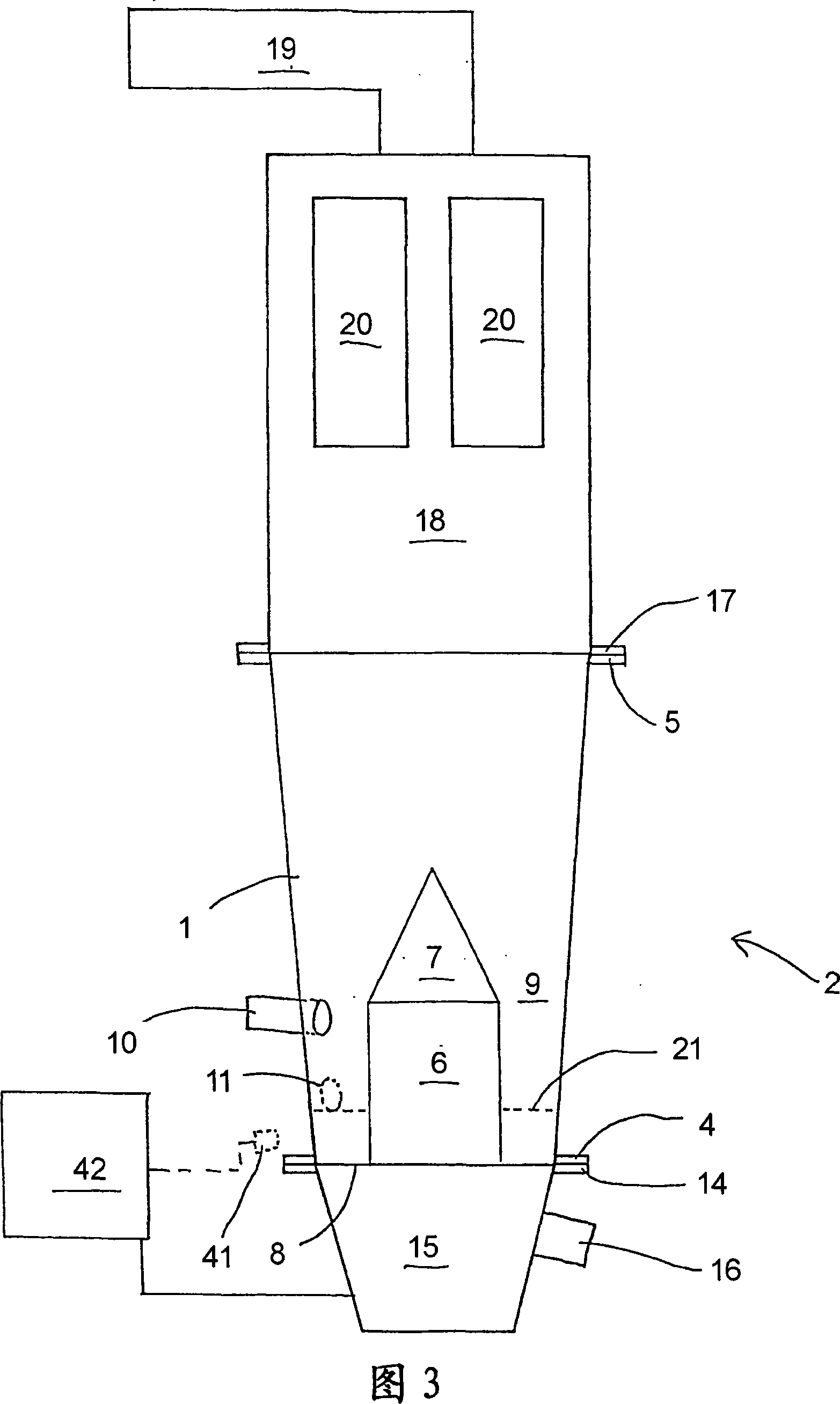
[0035] 1 and 2 show a fluidized bed plant module 1 for a fluidized bed plant as shown in FIG. 3 . The fluidized bed device 2 according to the invention can be used, for example, for drying partially dried but still moist powdered or granular products such as pharmaceuticals or nutraceuticals. The moist product to be dried in the fluidized bed device may have been produced, for example, in a spray drying process or in an extrusion process. In addition to drying, the unit is also suitable for granulation, agglomeration or coating. Although the device according to the invention is particularly suitable for the mentioned processes within the pharmaceutical industry, the invention can generally also be applied to other products and fluidized bed reactors.

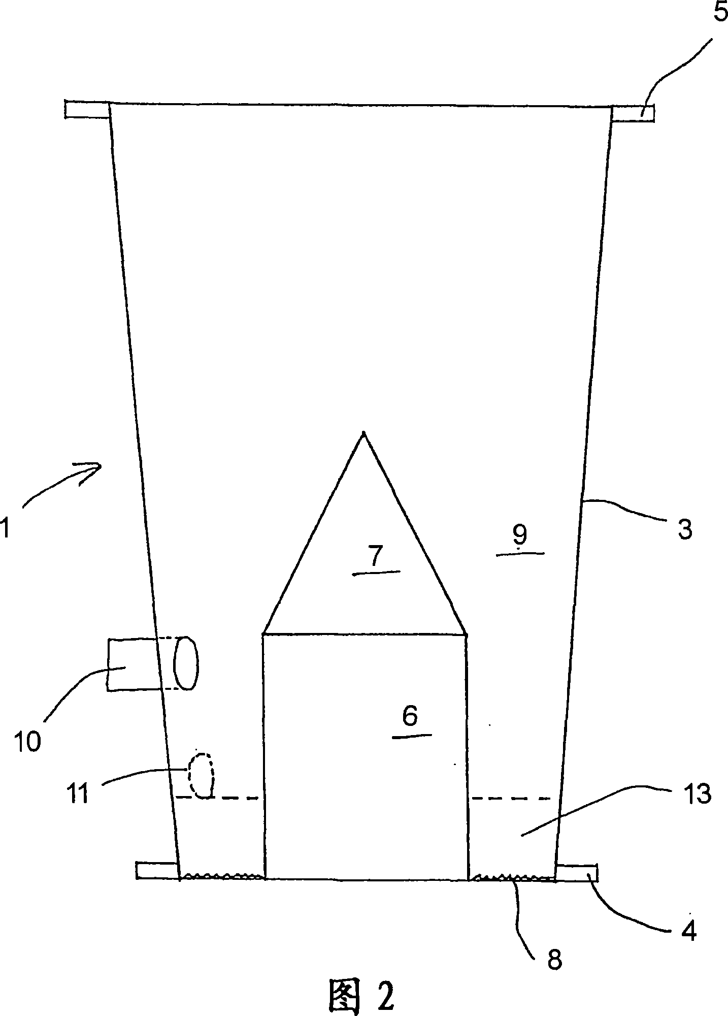
[0036] The fluidized bed plant module 1 shown in FIG. 2 comprises a conical outer wall 3 with a lower flange connection 4 and an upper flange connection 5 . A cylindrical core 6 is arranged concentrically with this outer wall ...


PUM


Abstract

The present invention discloses a fluid bed apparatus module (1), comprising an outer wall which encloses a processing chamber (9) and has a lower flange connection (4) and an upper flange connection (5). The lower flange connection is adapted to connection with a flange connection (14) of a supply of fluidizing gas, and the upper flange connection is adapted to connection with a flange connection (17) of a filter chamber (18) for gas discharge. At least one partition element (6) is arranged in the processing chamber, so that at least one elongated channel is formed in the processing chamber, thereby defining a plug-flow area, and at least one substantially continuous product inlet (10) and at least one substantially continuous product outlet (11) are arranged in the module. Furthermore, a method comprises changing a first module for a second module in a fluid bed apparatus.

Description

technical field [0001] The invention relates to a fluidized bed plant module comprising an outer wall enclosing a treatment chamber and having a lower flange connection and an upper flange connection, the lower flange connection being adapted to The flange connection of the fluidizing gas source is connected, and the upper flange connection is adapted to be connected with the flange connection of the filter chamber for gas discharge. Background technique [0002] US 5615493 (Niro Holding A / S) discloses a spray drying plant having a drying chamber with a continuous fluidized bed at the bottom. The fluidized layer is divided by a cylindrical partition wall into a first central region with backmixing and a second, plug-flow, surrounding channel-forming region. [0003] US 3723395 discloses a batch device for chemical reaction and drying operations. The apparatus consists of a cylindrical reactor with an internal flexible partition extending from the floor well above the expan...

Claims


Application Information

Patent Timeline
IPC IPC(8): B01J8/36B01J2/16F26B3/08
CPCB01J2208/00061B01J2219/00029B01J2208/00884B01J2219/00033B01J2219/0002B01J8/44B01J8/1809B01J2208/00557B01J2219/1946B01J2208/0084B01J2208/00699B01J2219/1944B01J8/34B01J2219/00031B01J8/36B01J2/16B01J2219/1943B01J2208/00548B01J8/006B01J2219/00024
Inventor O·E·汉森T·G·佩奇M·S·沃尔德伦
Owner 科里特股份有限公司
Why Eureka
Try Eureka