Scroll compressor with hot oil temperature responsive relief of back pressure chamber

A scroll compressor and back pressure chamber technology, applied in the field of scroll compressors, can solve problems such as insufficient provision of unfavorable conditions for faster release and the like

Inactive Publication Date: 2005-10-12
SCROLL TECH
View PDF0 Cites 33 Cited by
  • Summary
  • Abstract
  • Description
  • Claims
  • Application Information

AI Technical Summary

Problems solved by technology

To date, known scroll compressors do not adequately provide for faster release of adverse conditions

Method used


Image

  • Scroll compressor with hot oil temperature responsive relief of back pressure chamber
  • Scroll compressor with hot oil temperature responsive relief of back pressure chamber
  • Scroll compressor with hot oil temperature responsive relief of back pressure chamber

Examples


Embodiment Construction

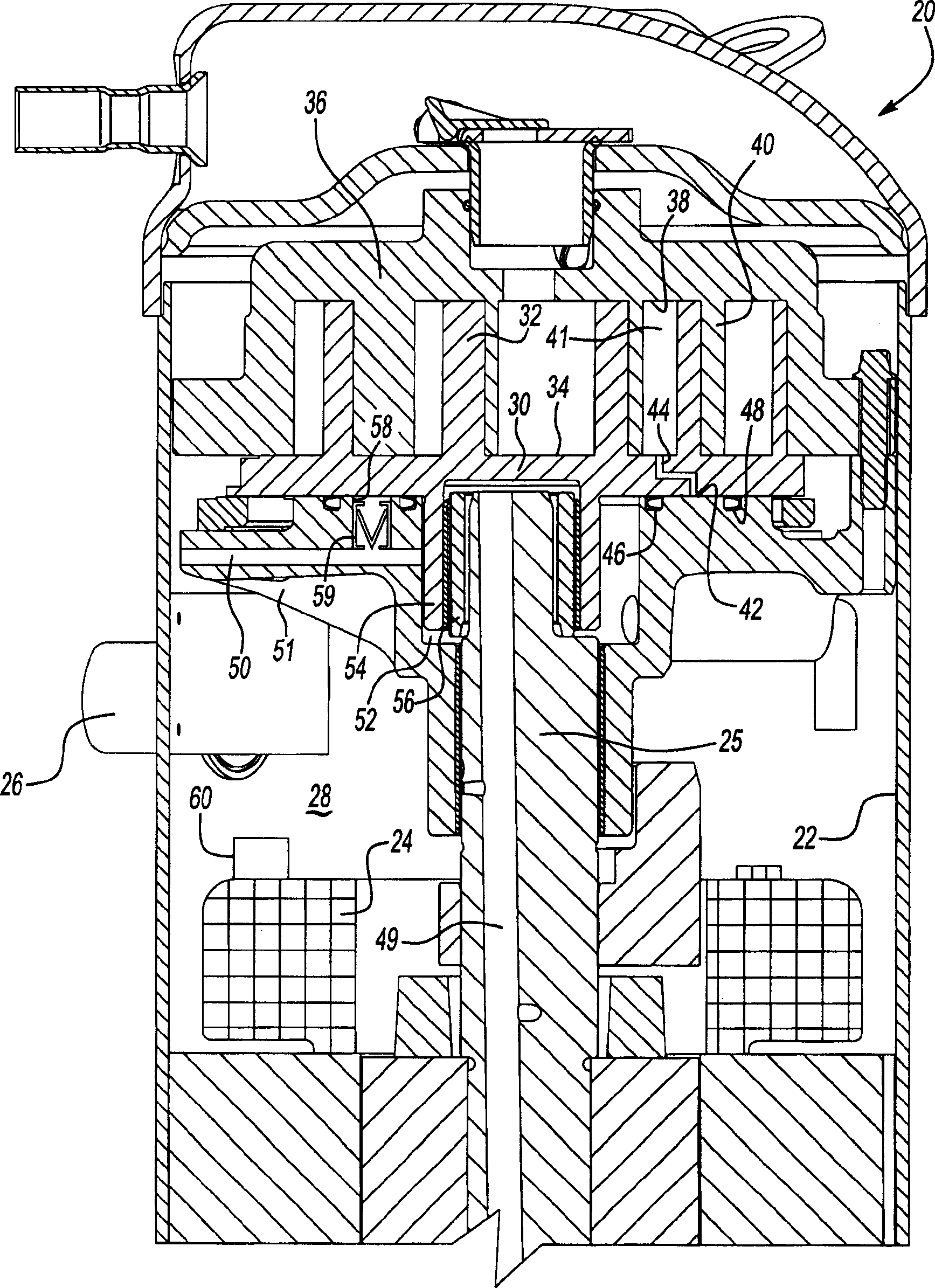
[0014] figure 1 A scroll compressor 20 is shown. Scroll compressor 20 is mounted within a sealed housing 22 . An electric motor 24 drives a shaft 25 to compress the refrigerant, as is known. Refrigerant enters the sealed housing 22 through the suction pipe 26 . A suction chamber 28 surrounds the motor through which refrigerant is drawn in to cool the motor.

[0015] A first scroll member 30 , known as an orbiting scroll, includes a helical outer shell 32 extending from a base 34 thereof. The scroll casings shown are of the so-called composite type, which have different thicknesses. Other types of scroll compressors are also within the scope of the present invention which include scroll casings formed on a circular involute, the casings of which have a relatively constant thickness. The orbiting scroll 30 faces a non-orbiting scroll 36 which has a base 38 in its own casing 40 extending from the base. As shown, the shells cooperate to define a compression chamber 41 . The...


PUM


Abstract

A scroll compressor includes a protection device that has a valve movable between a position blocking flow from the back pressure chamber into the suction chamber, and a position allowing such flow. The valve is movable dependent on an oil temperature. Under adverse conditions, the oil will reach higher temperatures and the valve will open allowing flow of refrigerant from the back pressure chamber into the suction chamber. This refrigerant will likely be at an elevated temperature, and will assist the heated oil in moving a motor protection switch associated with the motor to shut down the motor. Moreover, by relieving the back pressure chamber, the two scroll members are allowed to move out of contact with each other, thereby reducing potential damage due to the adverse conditions.

Description

Background technique [0001] The present application relates to a scroll compressor having a protection device that releases back pressure chamber refrigerant when the oil temperature reaches undesirably high values. Therefore, compared with the prior art, the present invention can solve some work problems better and faster. [0002] Scroll compressors are widely used in refrigerant compression applications. In a scroll compressor, each of a pair of scrolls has a base and a generally helical wrap extending from the base. These shells cooperate to define compression chambers. One of the two scrolls rotates relative to the other, and as the two scrolls rotate, the size of the compression chamber decreases, thereby compressing the collected refrigerant. As the refrigerant pressure increases, the separating force from the refrigerant tends to separate the two scroll members from each other. Accordingly, scroll compressor designers discharge a portion of the compressed refrigera...

Claims


Application Information

Patent Timeline
Patent Type & Authority Applications(China)
IPC IPC(8): F01C1/02F04C18/00F04C18/02F04C28/26F04C28/28F04C29/04
CPCF04C28/265F04C28/28F04C2270/19F04C18/0215F04C2270/21
Inventor T·P·帕特尔
Owner SCROLL TECH
Why Eureka
Try Eureka