Frame structure
A frame and component technology, applied in the field of frame structures, can solve the problems of no known patent documents and the inability to use scaffolding, etc.
- Summary
- Abstract
- Description
- Claims
- Application Information
AI Technical Summary
Problems solved by technology
Method used
Image

Examples
Embodiment Construction
[0018] Hereinafter, embodiments of the present invention will be described together with illustrated examples.
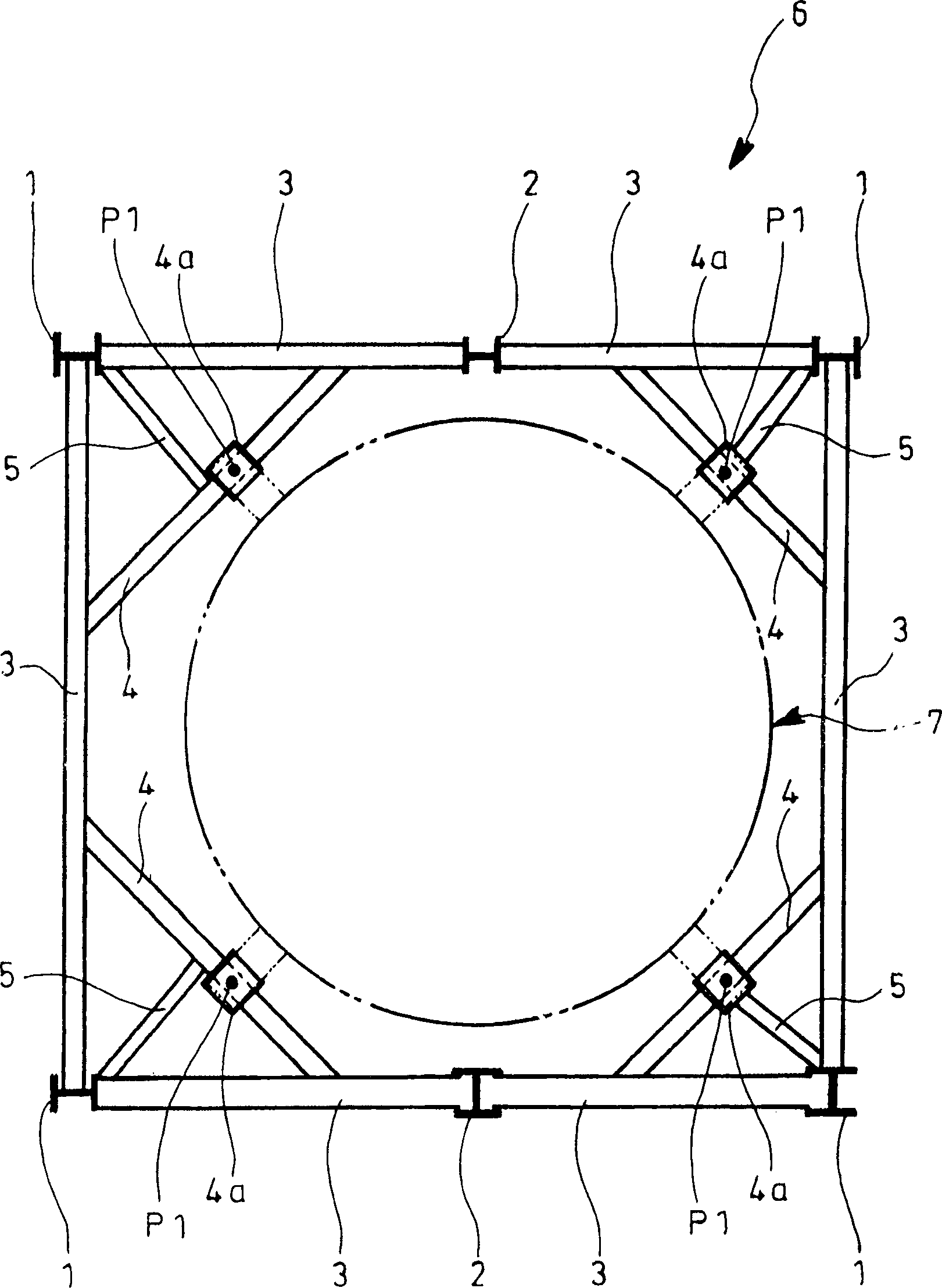
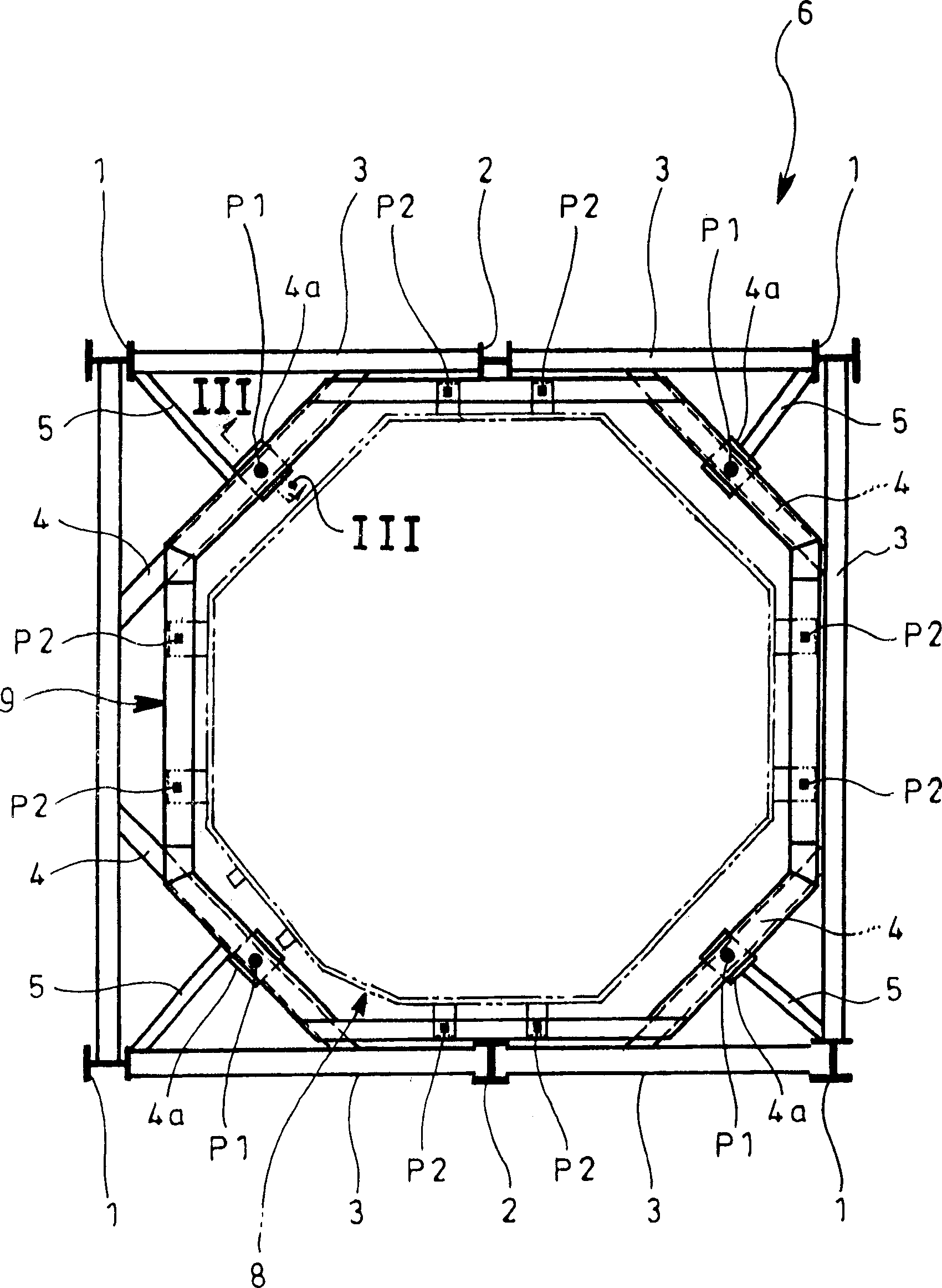
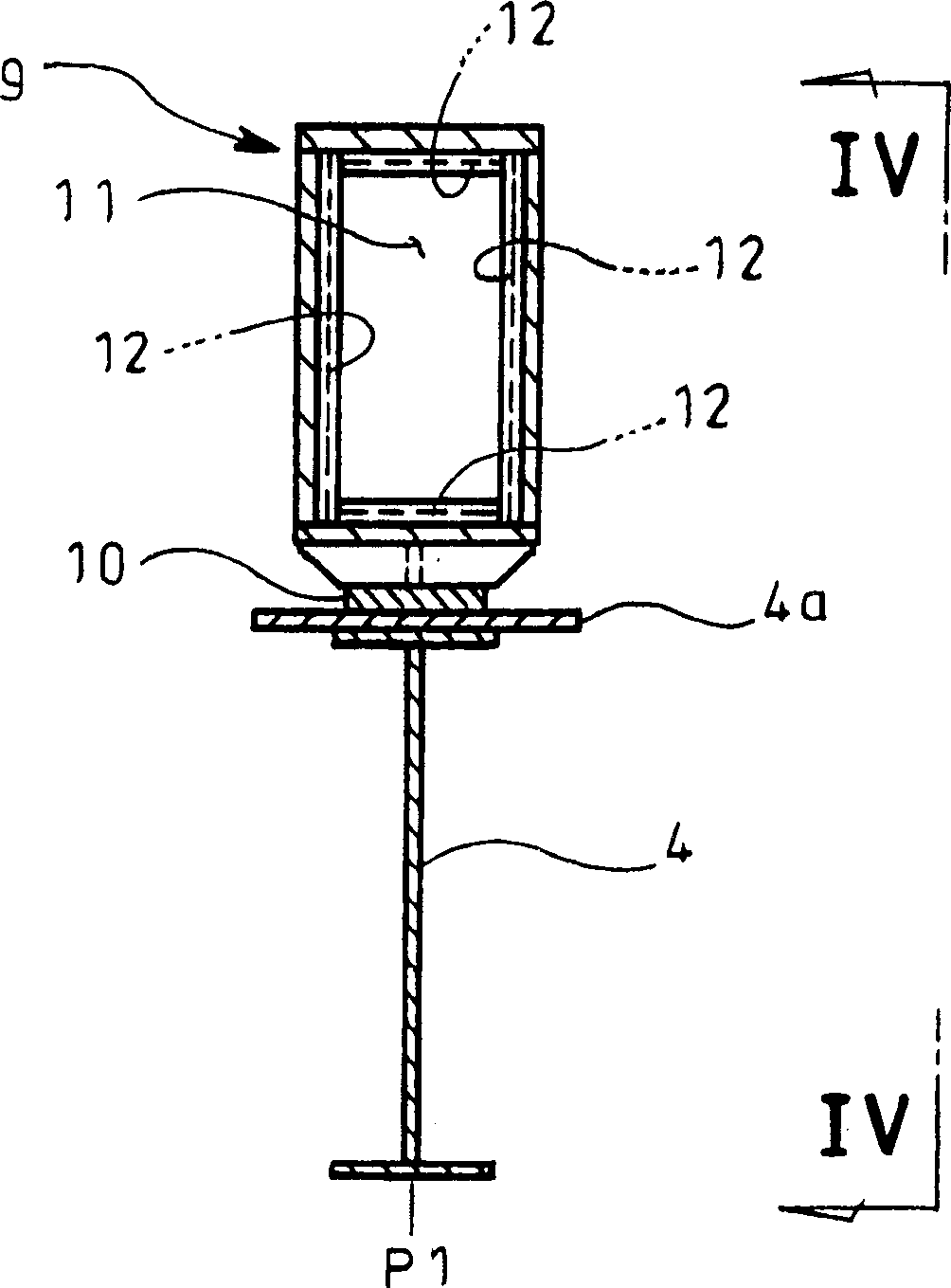
[0019] Figure 2 ~ Figure 4 is an example of the manner of implementing the present invention, in the figure, marked with figure 1 The part of the same symbol represents the same component, and the basic structure of the frame structure of the present invention is the same as figure 1 The previous frame structure shown is the same, but as Figure 2 ~ Figure 4 As shown, the feature of the example shown in this figure is that it is provided with: ring beam 9, which is relative to the load support point P1 of the fixed air preheater 7 as a part of the existing machine on the frame 6, and transfers it as a new design. Mechanical components The load of the rotary air preheater 8.
[0020] In the case of the example shown in this figure, the load of the rotary air preheater 8, which is a newly installed mechanical component, acts on the load support point P2 of the rin...
PUM
 Abstract
Description
Claims
Application Information