Automatically inverting and overturning type toilet seat
A technology of automatic turning and toilet, which is applied in the field of sanitary equipment, can solve the problems of complex structure, inconvenient manufacture and use, etc., and achieve the effect of excellent anti-odor effect, reliable performance and easy manufacture
- Summary
- Abstract
- Description
- Claims
- Application Information
AI Technical Summary
Problems solved by technology
Method used
Image
Examples
Embodiment 1
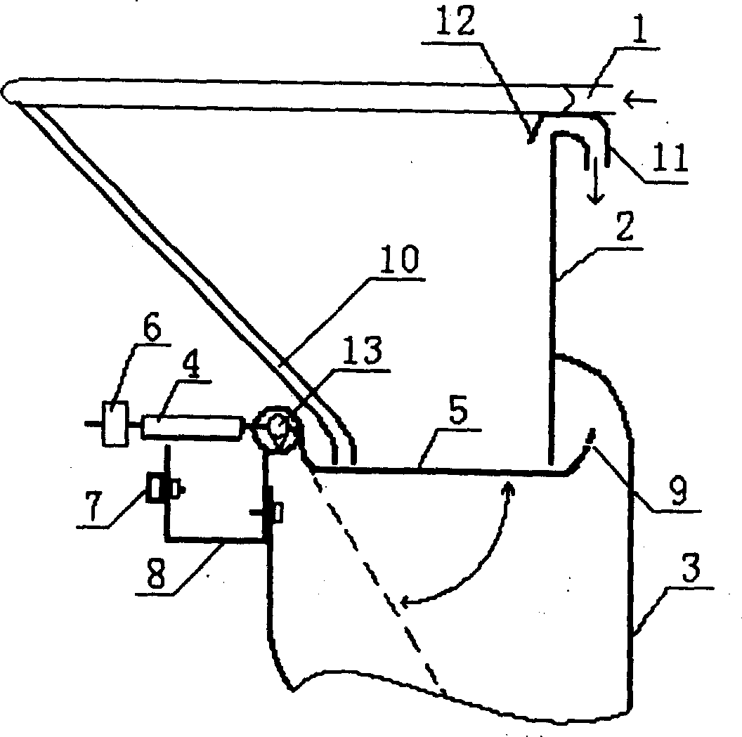
[0029] Embodiment one, such as figure 1 and 5 As shown, the automatic turning and dumping toilet of the present invention includes a body 2 with a water inlet 1 at the upper end and a base 3 connected thereto. The lower port of the body 2 is equipped with a flip-type loading tray 5 . The loading tray 5 is a trough-shaped tray that can store water. The loading tray 5 forms a lever structure with the counterweight 4 arranged at the other end through the support shaft 13 . The counterweight body 4 is equipped with an adjustable counterweight nut 6 by bolts. Counterweight body 4 is made of ferrous material. The bottom of the counterweight 4 is equipped with a permanent magnet 7, and the permanent magnet 7 is fixed on the loading tray support 8 with vertical slots through standard parts. The tray support 8 is fixed with the base 3 . An overflow hole 9 is provided on the end side wall of the loading tray 5 . A flushing channel 10 corresponding to the base of the loading tray ...
Embodiment 2
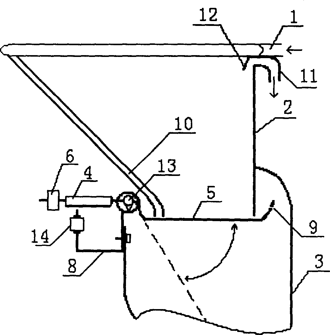
[0030] Embodiment two, such as figure 2 and 5 As shown, the water inlet 1, the body 2, the base 3, the loading tray 5, the counterweight body 4, the counterweight nut 6, the loading tray support 8, the loading tray overflow hole 9, the flushing water channel 10, the drain The structures and materials of the tuyere 11, its baffle plate 12, and the support shaft 13 are the same as those in the embodiment. The bottom of counterweight body 4 is provided with electromagnetic coil 14, and electromagnetic coil 14 is fixed on the vertical screw rod of loading tray support 8 by nut, and electromagnetic coil 14 is equipped with the switch of DC power supply and exhaust fan linkage. The introduction of the electromagnetic coil 14 is to offset the load of the loading tray with its magnetic force to prevent the loading tray 5 from turning over accidentally.
Embodiment 3
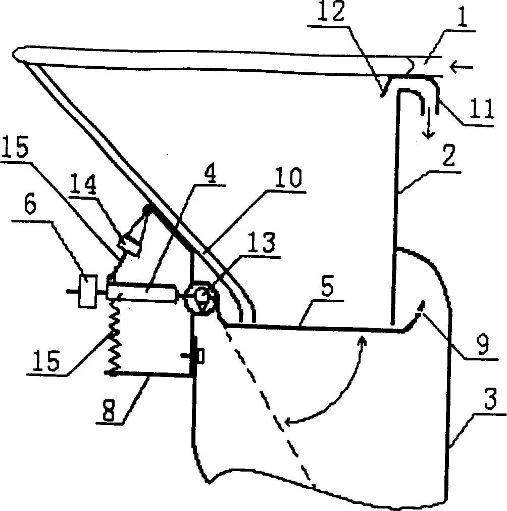
[0031] Embodiment three, such as image 3 , 4 Shown in and 5, water inlet 1, body 2, base 3, loading tray 5, counterweight body 4, counterweight nut 6, loading tray overflow hole 9, flushing water channel 10, air outlet 11 and The structures and materials of the baffle plate 12 and the support shaft 13 are the same as those in the embodiment. An electromagnetic coil 14 is arranged above the counterweight body 4 and is hinged on the carrier tray support 8 . The counterweight body 4 is hinged to a ferrous material rod 15 , and the electromagnetic coil 14 is provided with a sliding matching hole matched with the ferrous material rod 15 . The ferrous material rod 15 and the electromagnetic coil 14 are located on the same arc with the support shaft 13 as the center. Device extension spring 16 between counterweight body 4 and the loading tray support 8 below. The electromagnetic coil 14 is equipped with a DC power supply and a switch linked with the flush valve. The loading tra...
PUM
 Abstract
Description
Claims
Application Information
 - R&D
- Intellectual Property
- Life Sciences
- Materials
- Tech Scout
- Unparalleled Data Quality
- Higher Quality Content
- 60% Fewer Hallucinations
Browse by: Latest US Patents, China's latest patents, Technical Efficacy Thesaurus, Application Domain, Technology Topic, Popular Technical Reports.
© 2025 PatSnap. All rights reserved.Legal|Privacy policy|Modern Slavery Act Transparency Statement|Sitemap|About US| Contact US: help@patsnap.com


