Reactor arrangement for carrying out catalytic gas reactions

A reaction device and phase reaction technology, applied in the chemical method, installation, organic chemistry and other directions of reacting gaseous medium with gaseous medium, can solve the problems of uneven load of cooling pipe, inconvenient maintenance, high cleaning cost, etc. The effect of reducing the risk of subsequent reactions, reducing cleaning costs, and reducing operating costs

Active Publication Date: 2005-11-16
MAN ENERGY SOLUTIONS SA
View PDF3 Cites 6 Cited by
  • Summary
  • Abstract
  • Description
  • Claims
  • Application Information

AI Technical Summary

Problems solved by technology

In addition, different reaction gas cooling over the tube bundle cross-section leads to uneven loading of the cooling tubes, which in turn leads to more deposits in the cooling tubes
Due to the integral structure of the aftercooler which is fixedly connected to the reactor by means of welded connections, this reaction device is not easy to maintain, and the tendency to generate more deposits leads to very high cleaning costs

Method used


Image

  • Reactor arrangement for carrying out catalytic gas reactions
  • Reactor arrangement for carrying out catalytic gas reactions
  • Reactor arrangement for carrying out catalytic gas reactions

Examples


Embodiment Construction

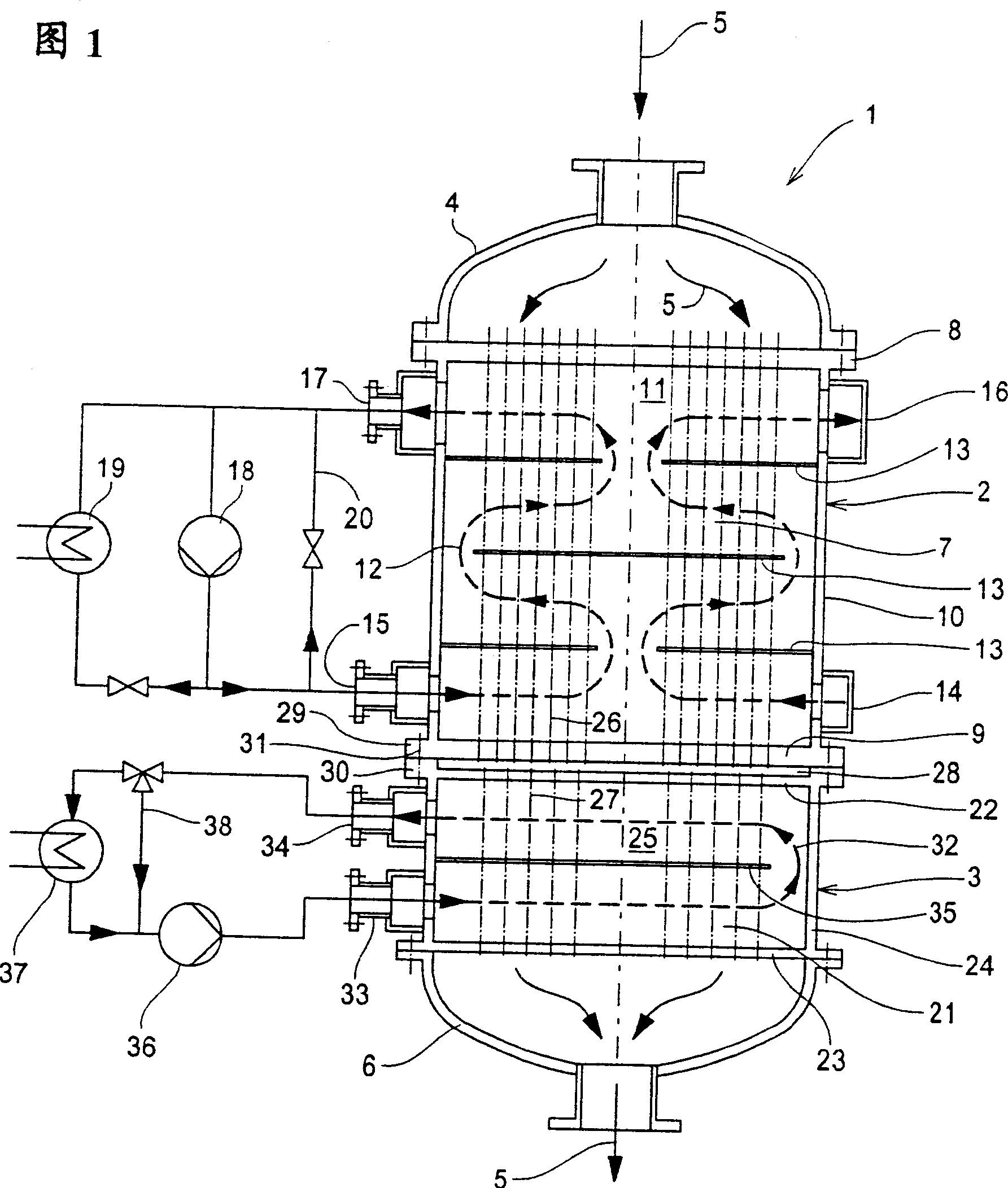
[0036] The shown exemplary embodiment of the reaction apparatus 1 according to the invention has a tubular reactor 2 and an aftercooler 3 connected directly downstream therefrom. The reaction gas 5 is introduced into the jacketed reactor 2 through a gas inlet hood 4 . After flowing through the jacketed reactor 2 and the aftercooler 3 , the reaction gas 5 is removed from the reaction device 1 by means of a gas outlet hood 6 .

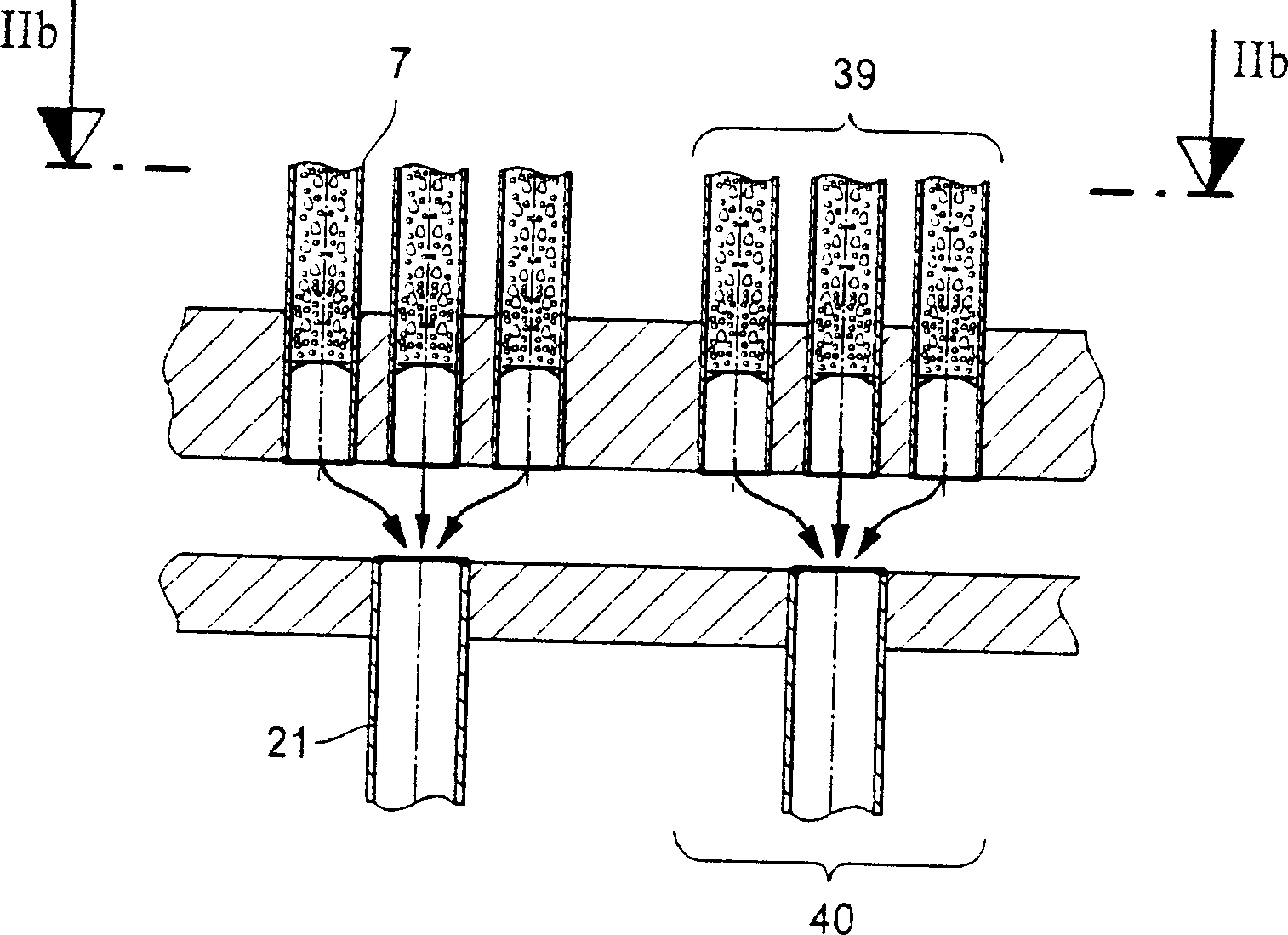
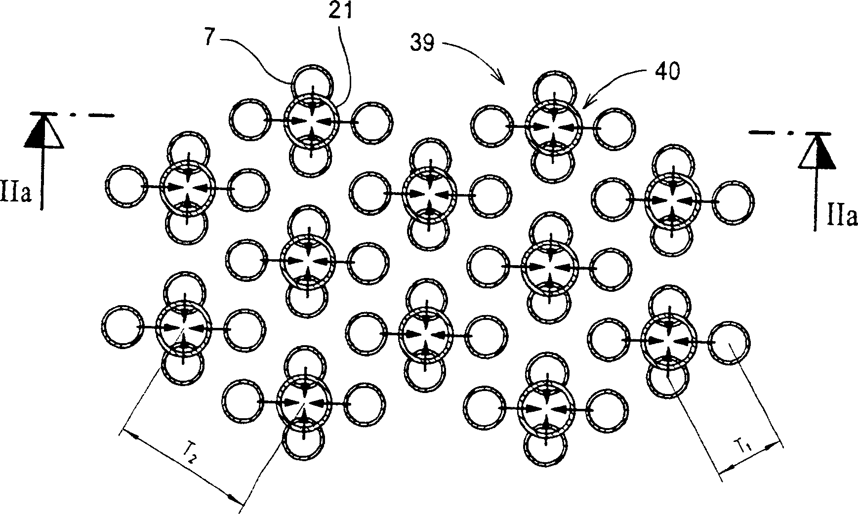
[0037] The jacketed reactor 2 (FIG. 1) comprises a plurality or bundle of catalyst-filled reaction tubes 7 extending vertically between an upper tube base 8 and a lower tube base 9 and surrounded by a cylindrical sleeve 10, in which The outer sides of the two ends of the reaction tube 7 are gas-tightly welded to the corresponding tube bottoms 8 and 9 . A tubeless zone 11 is formed at the center of the reaction tube bundle 7 .

[0038] The reaction tubes are sprayed / rinsed around by a heat transfer medium 12 which passes through the reaction tube bundle...


PUM


Abstract

Reactor arrangement (I), for carrying out catalytic gaseous phase reactions, comprises a jacket tube reactor (2), a bundle of tubes and a separate, after cooler (3) directly connected to the side outlet, where the cross sectional area in the after cooler is essentially congruent with the cross sectional area in the jacket and both the cross sectional areas are oppositely paired in large numbers. - Reactor arrangement (I), for carrying out catalytic gaseous phase reactions, comprises a jacket tube reactor (2), a bundle of tubes with a number of catalyst-filled reaction tubes surrounded by the jacket, (where the reaction bundle of tubes lies in a cross sectional area perpendicularly to the longitudinal axis of the reaction tubes) and a separate, after cooler (3) directly connected to the side outlet (where the reaction tubes with the cooling tubes is surrounded by the envelope, the number of the cooling tubes is less than the reaction tube and the cooling tubes lies in a cross sectional area perpendicularly to the longitudinal axis of the cooling tubes (21)), where the cross sectional area (26, 27) in the after cooler is essentially congruent with the cross sectional area in the jacket tube reactor and both the cross sectional areas are oppositely paired in large numbers and in large parts with essentially same ratio of current cross-section of cooling tubes to the lower current cross section of the reaction tubes (7).

Description

technical field [0001] The invention relates to a reaction device for realizing a catalytic gas phase reaction, which has a sleeve reactor, which has a bundle of reaction tubes surrounded by a sleeve and filled with a large number of catalysts. Wherein the reaction tube bundle has a cross-sectional area with tube holes perpendicular to the longitudinal axis of the reaction tube; it also has a separate aftercooler directly connected to the back, which has a cooling tube bundle surrounded by a sleeve, the number of cooling tubes Fewer than the number of reaction tubes, wherein the cooling tube bundle also has a cross-sectional area with tube holes perpendicular to the longitudinal axis of the cooling tubes. The invention also relates to the use of such a reaction device for realizing various catalytic gas phase reactions. Background technique [0002] In many gas phase reactions it is important to suppress the other reactions quickly after the desired reaction has ended so th...

Claims


Application Information

Patent Timeline
Patent Type & Authority Applications(China)
IPC IPC(8): B01J8/06B01J12/00C07B61/00F28D7/00F28D7/16F28F9/02F28F9/26
CPCB01J2219/185F28D7/0091B01J12/00B01J2208/00221B01J8/067F28D7/0066F28F9/0229F28D7/1607B01J2208/00274F28F9/26F28F2280/105B01J2208/00194B01J2208/0053
Inventor F・盖特乌贝尔M・莱勒
Owner MAN ENERGY SOLUTIONS SA
Why Eureka
Try Eureka