Optical information recording medium and manufacturing method thereof
一种记录介质、光学信息的技术,应用在光学记录载体制造、光学记录/再现/擦除方法、光学记录载体等方向,能够解决成膜周期长时间等问题,达到抑制成膜速度的变化、良好记录灵敏度的效果
- Summary
- Abstract
- Description
- Claims
- Application Information
AI Technical Summary
Problems solved by technology
Method used
Image
Examples
Embodiment 1
[0041] One embodiment of the optical information recording medium will be described. The optical information recording medium of the present invention is a recording medium including a plurality of information layers separated from each other by an optical separation layer. In this embodiment, as an example, an optical information recording medium including two information layers will be described.
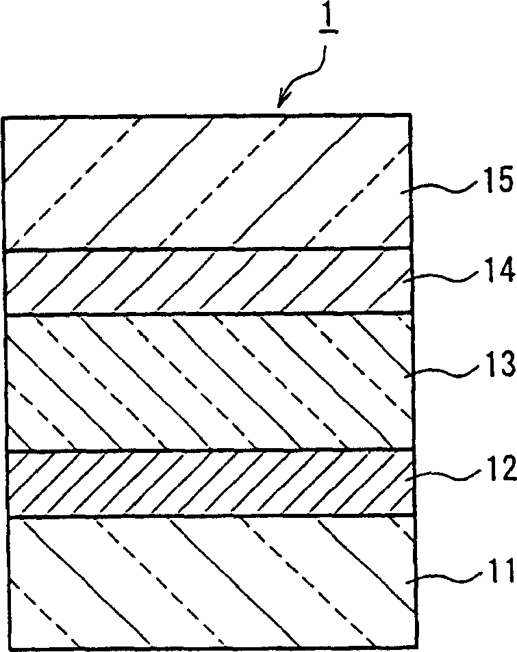
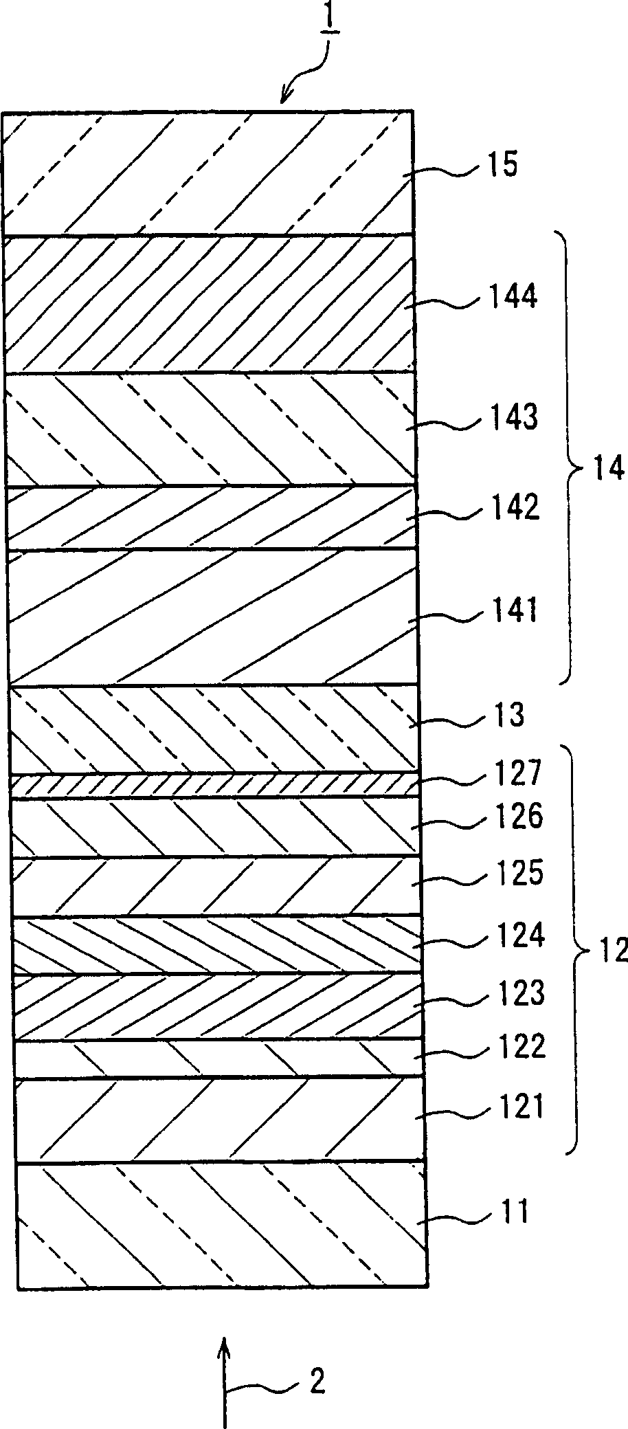
[0042] figure 1 A cross-sectional view showing a schematic multilayer structure in the radial direction of a disc-shaped optical information recording medium 1 (hereinafter referred to as "optical disc 1") of the present embodiment is shown. Such as figure 1 As shown, in the optical disc 1, a first substrate 11, a first information layer 12, an optical separation layer (first optical separation layer) 13, a second information layer 14, and a second substrate 15 are sequentially stacked. Each of the two information layers 12, 14 laminated together via the optical separation la...
Embodiment 2
[0089] One embodiment of the manufacturing method of the optical information recording medium of the present invention will be described. In this embodiment, the optical disc 1 introduced in Embodiment 1 (see figure 2 ) method of manufacture.
[0090] First, the second information layer 14 is formed on the second substrate 15 . More specifically, first, second substrate 15 (for example, with a thickness of 1100 μm) is prepared, and placed in a film forming apparatus.
[0091] Then, a reflective layer 144 is formed on the second substrate 15 . It can be formed by sputtering using a sputtering target containing elements constituting the reflective layer 144 in an Ar atmosphere or an atmosphere of a mixed gas of Ar gas and active gas (at least one gas selected from oxygen and nitrogen). reflective layer 144 . In this case, when forming the guide groove for guiding the laser beam 2 to the second substrate 15, the reflective layer 144 is formed on the surface on the side where...
Embodiment 3
[0113] In Embodiment 3, an example of a method of recording / reproducing information on the optical disc 1 as described in Embodiment 1 will be described.
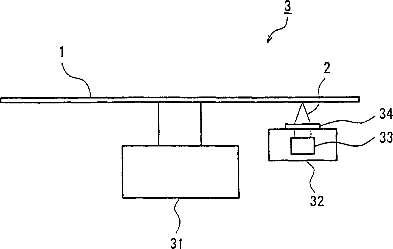
[0114] First, the recording / reproducing apparatus used in the recording / reproducing method in this embodiment will be described. image 3 The configuration of a part of the recording / reproducing device 3 used in the recording / reproducing method of this embodiment is schematically shown. The recording / reproducing device 3 includes a spindle motor 31 for rotating the optical disc 1 , an optical head 32 having a semiconductor laser 33 , and an objective lens 34 for focusing the laser beam 2 emitted from the semiconductor laser 33 . The optical disc 1 is the optical information recording medium described in Embodiment 1, and includes two information layers (the first information layer 12 and the second information layer 14). The first information layer 12 includes a recording layer 123 , and the second information layer 14 inc...
PUM
| Property | Measurement | Unit |
|---|---|---|
| wavelength | aaaaa | aaaaa |
| diameter | aaaaa | aaaaa |
| wavelength | aaaaa | aaaaa |
Abstract
Description
Claims
Application Information
 - R&D
- Intellectual Property
- Life Sciences
- Materials
- Tech Scout
- Unparalleled Data Quality
- Higher Quality Content
- 60% Fewer Hallucinations
Browse by: Latest US Patents, China's latest patents, Technical Efficacy Thesaurus, Application Domain, Technology Topic, Popular Technical Reports.
© 2025 PatSnap. All rights reserved.Legal|Privacy policy|Modern Slavery Act Transparency Statement|Sitemap|About US| Contact US: help@patsnap.com


