Tray drive

A driving device and tray technology, which is applied in recording information storage, instruments, etc., can solve the problems of increased component cost and complex structure, and achieve the effect of reducing impact and avoiding rapid changes.

Inactive Publication Date: 2005-12-14
FUNAI ELECTRIC CO LTD
View PDF5 Cites 3 Cited by
  • Summary
  • Abstract
  • Description
  • Claims
  • Application Information

AI Technical Summary

Problems solved by technology

Then, the structure becomes more complicated compared to providing two limit switches, and therefore, a significant increase in cost of parts is involved
[0006] Furthermore, in the case of utilizing the second related art, a current detection circuit (voltage detection circuit) for detecting the drive motor current, and an operational amplifier indispensable to the current detection circuit (voltage detection circuit) are required, therefore, Also involves increased component costs

Method used


Image

  • Tray drive
  • Tray drive
  • Tray drive

Examples


Embodiment Construction

[0032] Embodiments of the present invention are described below with reference to the drawings.

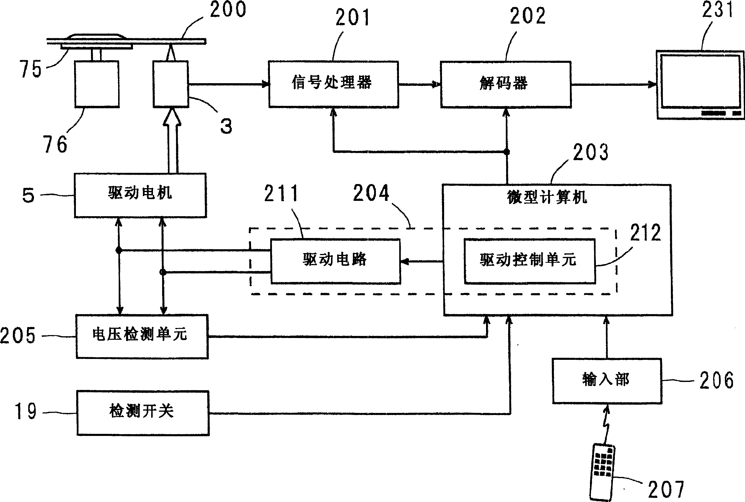
[0033] Figure 5 Shows the appearance of an optical disc device equipped with an embodiment of the tray driving device according to the present invention.

[0034] The optical disc device 100 is a device that loads an optical disc such as a DVD placed on a tray 2, in which the loaded optical disc is irradiated with a laser beam to record or reproduce a signal. When the tray 2 on which the disc is placed is moved back and forth between the retracted position and the ejected position (arrow A shows the direction of movement) by the tray driving mechanism, loading or ejecting of the disc is performed. The movement of the tray 2 to the retracted position is detected by a tray position detection unit (described later in detail), but the unit for detecting the movement of the tray 2 to the retracted position is omitted.

[0035] Figure 6 Indicates that the tray drive mechanism is in...


PUM


Abstract

The device disclosed in the present invention includes a tray drive mechanism that uses a drive motor as a power source to move the tray back and forth; After a predetermined duration elapses from the moment when the tray is considered to have moved to the exit position, the motor drive unit gradually reduces the voltage applied to the drive motor, so that the voltage drops from the first drive voltage to 0V.

Description

technical field [0001] The present invention relates to a tray driving device for reciprocatingly moving a tray on which an optical disc is placed between an ejected position and a retracted position, and more particularly, to a device that eliminates the need for a switch for detecting that the tray has moved to the ejected position tray drive. Background technique [0002] A digital video disc (DVD) player is provided with a tray for placing a DVD thereon. To replace the DVD, the drive motor moves the tray toward the ejected position until the limit switch detects that the tray has moved to the ejected position. Also, to play a DVD placed on the tray, the drive motor moves the tray toward the retracted position until the limit switch detects that the tray has moved to the retracted position (see, for example, JP-A-2000-285561 and JP-A- 2001-243687). Furthermore, a switch for detecting the moving direction of the tray is provided, and the movement of the tray is controll...

Claims


Application Information

Patent Timeline
Patent Type & Authority Applications(China)
IPC IPC(8): G11B17/056G11B17/04
CPCG11B17/056
Inventor 坂上胜哉
Owner FUNAI ELECTRIC CO LTD
Why Eureka
Try Eureka