Method for synchronising an analog display of a timepiece with its electronic time base

A display and electronic technology, used in clocks and watches, indicating time, instruments, etc. by visual means, can solve problems such as determining distortion

Active Publication Date: 2005-12-28
THE SWATCH GRP RES & DEVELONMENT LTD
View PDF2 Cites 5 Cited by
  • Summary
  • Abstract
  • Description
  • Claims
  • Application Information

AI Technical Summary

Problems solved by technology

Over a very long period of time, the temperature of the clock will vary greatly by more than 2°C, so that the reference angle α REF Deterministic distortion of

Method used


Image

  • Method for synchronising an analog display of a timepiece with its electronic time base
  • Method for synchronising an analog display of a timepiece with its electronic time base
  • Method for synchronising an analog display of a timepiece with its electronic time base

Examples


Embodiment Construction

[0025] The following will refer to Figure 5 A timepiece 40 for implementing the synchronization method of the present invention is schematically illustrated.

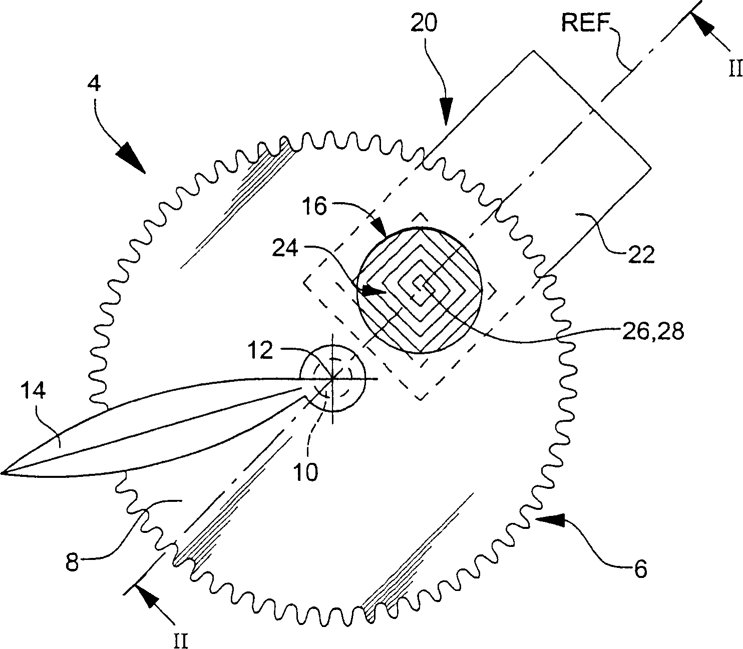
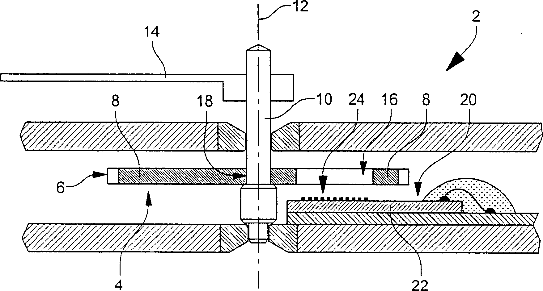
[0026] Timepiece 40 includes an analog display 41 of the current time. The display includes an hour indicator 42 and a minute indicator 44 . Indicators 42 and 44, in particular formed by conventional hands, are rotatably connected to a first wheel 46 and a second wheel 48, respectively. Two stepper motors 50 and 52 drive the two wheels 46 and 84 respectively. as previously referenced figure 1 As noted, wheels 46 and 48 have openings 54 and 56, respectively, in their base plates formed of electrically conductive material. Non-contact inductive sensors 60 and 62 are associated with the first and second wheels for detecting apertures 54 and 56 respectively to precisely determine the angular position of indicators 42 and 44 .

[0027] The angular position of the wheel is no longer specified here, especially the previ...


PUM


Abstract

The present invention discloses a method of calibrating an analog display (41) of a timepiece (40) including an electronic time base (64) using an aperture (54, 56) each having an opening (54, 56) therein for defining the angular position of the wheel. Non-contact sensors (60, 62) associated with the wheels (46, 48) are implemented. Determining the angular position of the wheel requires a non-contact sensor of this type to travel an angular distance of 60° to 90°. Given that angles of 60° to 90° correspond to time intervals of 2 to 3 hours, the temperature dependence of the measurement results creates problems with the accuracy of the determination of the angular position of the wheel, especially the wheel fixed to the hour indicator. In order to ensure that the measurement is carried out within a short time interval in which the ambient temperature is essentially constant so as not to affect the measurement, the present invention proposes measurement in an analog display synchronization mode, in which at least one indicator is driven in an accelerated forward mode so that the opening on the corresponding wheel The hole zips past the non-contact sensor associated with the wheel.

Description

technical field [0001] The invention relates to a method of calibrating the analog display of a timepiece with an electronic time base mounted on its movement. A quartz oscillator well known to those skilled in the art is mounted on this time base. The analog display includes an analog indicator rotatably coupled to the wheel of the first watch movement. Within the scope of the invention, the first wheel is associated with a proximity sensor and has at least one opening in the base plate of the wheel, preferably made of electrically conductive material. Non-contact sensors are used to detect the opening of the first wheel, and more specifically to determine the position of a reference geometric semi-axis defined by said opening. [0002] In particular, said analog indicator is a time indicator. Background technique [0003] EP Patent No. 0952426 discloses in particular the principle of detection of a semi-axis defined by an aperture provided in a wheel connected to an ana...

Claims


Application Information

Patent Timeline
Patent Type & Authority Applications(China)
IPC IPC(8): G01D5/20G01D18/00G04B18/00G04B19/04G04C3/00G04C3/14
CPCG01D5/202G04C3/14
Inventor E·贝尔纳斯科尼R·比勒R·丁格P-A·法里纳
Owner THE SWATCH GRP RES & DEVELONMENT LTD
Why Eureka
Try Eureka