Supercharge Your Innovation With Domain-Expert AI Agents!

Equipment with printing function

A technology of printing functions and equipment, applied in printing devices, printing, typewriters, etc., can solve problems such as low sound, time delay, and difficulty for chefs to perceive

Inactive Publication Date: 2006-01-04
SHANDONG NEW BEIYANG INFORMATION TECH CO LTD
View PDF0 Cites 0 Cited by
  • Summary
  • Abstract
  • Description
  • Claims
  • Application Information

AI Technical Summary

Problems solved by technology

The environment in the kitchen is relatively bad, the smoke reduces visibility, and various environmental noises are also relatively large.
At present, the printers used in the kitchen generally have a relatively low sound when printing order information, and the volume of the indicator light is also relatively small, which cannot indicate the status of the printer in a timely and obvious manner.
When new order information is printed out, due to the influence of smoke, environmental noise, and distance, it is not easy for the chef to notice it. Even if the indicator light of the printer keeps flashing after the printing is completed, it is difficult to attract attention due to its small size
In this way, the order information that has been printed cannot be obtained in time, and the time is delayed.
In the electronic ordering system, if the customer's ordering information cannot be read in time, it will cause a time delay, which will affect the normal and timely operation of the entire electronic ordering system, and cause irreparable damage to the image of the restaurant.
It can be seen from the above that the printers in the existing ordering system have the disadvantage of not having long-distance prompts in time

Method used


Image

  • Equipment with printing function
  • Equipment with printing function
  • Equipment with printing function

Examples


Embodiment 1

[0019] In this embodiment, the device with printing function is a printer.

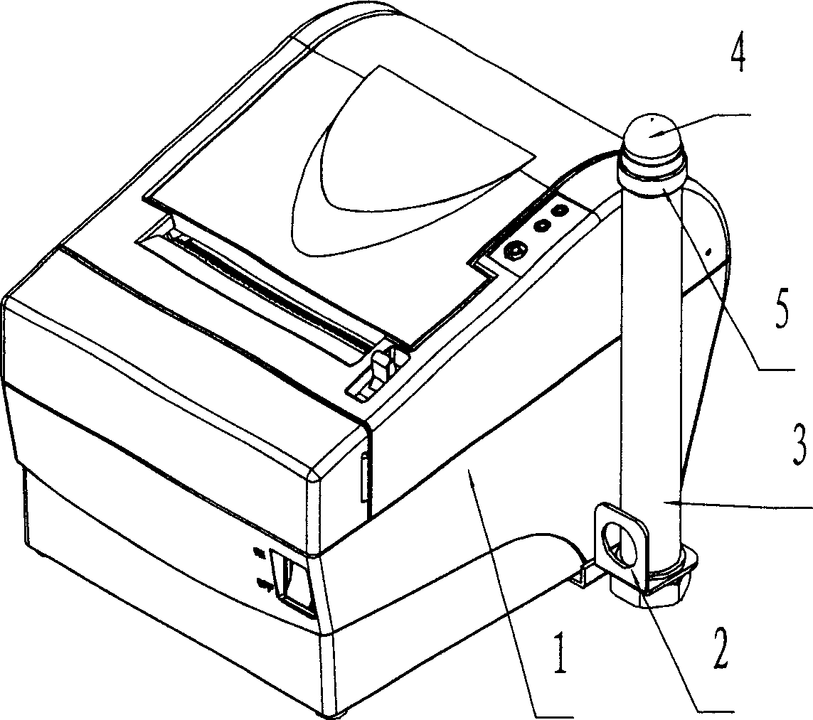
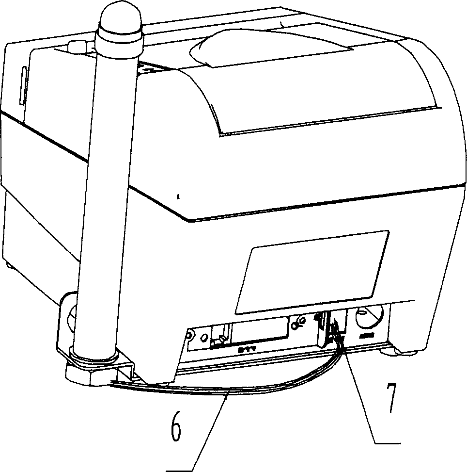
[0020] Such as figure 1 As shown, the printing indicating device 4 set in the printer of this embodiment is a light emitting device, the light emitting device is set to a light emitting diode, a fixing frame 2 is provided outside the casing 1, a fixing rod 3 is set on the fixing frame, and a fixing rod 3 is set to be fixed. The base 5, the light emitting diode is installed on the fixed base 5. by figure 2 It can be seen that the print indicating device 4 is connected to the cash box interface 7 of the printer through the wire 6, and the cash box interface 7 is connected to the CPU 8 of the printer control unit.

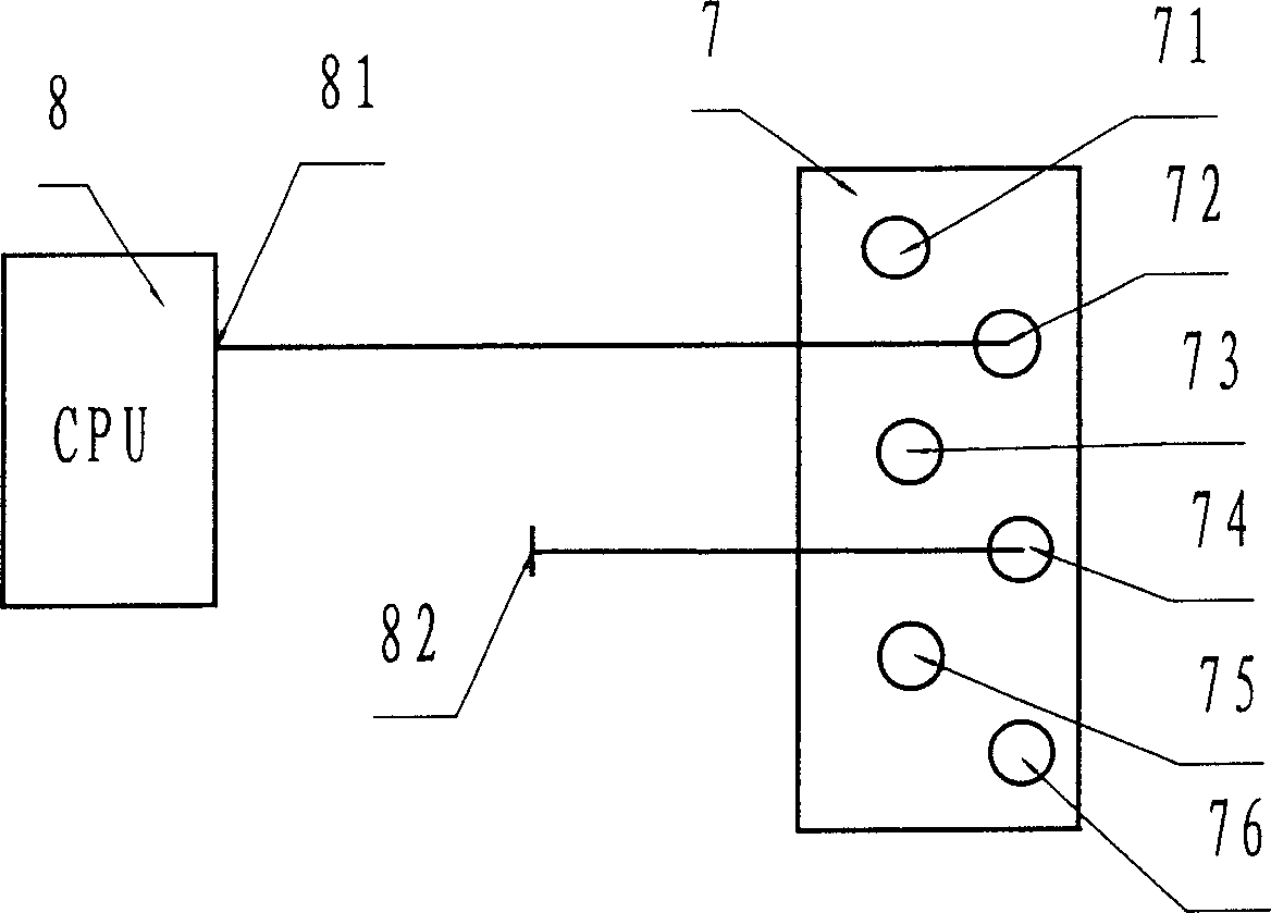
[0021] The function process of this embodiment in the use process is as follows, such as image 3 , 4 As shown, when printing is required, the printer sends instructions to CPU8, and CPU8 controls the level of its output signal control pin, thereby controlling the level of the corresponding pin...

Embodiment 2

[0034] The difference between this embodiment and Embodiment 1 is that the cash drawer interface 7 of this embodiment is connected to the printing indicating device in a wireless connection, and wireless technology such as infrared technology, Bluetooth technology, radio frequency technology, etc. can be used for connection.

[0035] Such as Figure 5 As shown, this embodiment is provided with a wireless transmitting module 9 at the cash drawer interface 7. The control terminal 91 of the wireless transmitting module is connected to the second pin 72 of the cash drawer interface, and the pin 92 of the wireless transmitting module is connected to the cash drawer interface. The fourth pin 74 is connected, so that the wireless transmitting module 9 and the cash drawer interface 7 are connected.

[0036] Such asFigure 6 As shown, a wireless receiving module 10 is provided at the printing indicating device 4, and both ends of the wireless receiving module are respectively connected to t...


PUM


Abstract

The present invention relates to equipment with printing function, and is especially one kind of equipment with printing function and capable of being connected with external indication device to provide the user with timely and efficient printed output information prompt. The equipment includes one printing unit, and one control unit with CPU and external print indication device connected directly or indirectly with the CPU. The present invention also discloses one preferable implementation example.

Description

Technical field [0001] The invention relates to a device with a printing function, in particular to a device with a printing function that can be connected to an external indicating device. Background technique [0002] As a new technology, printing technology has been widely used in various application fields such as life, production, logistics, and entertainment. With the increase in demand diversity, printing functions have been added to many devices, such as information query terminals, automatic teller machines, and so on. Among them, the printer is the most widely used as a kind of information output device. With the expansion of the application range of printers, the need for remote printing has gradually emerged, that is, the operator sends printing instructions to the printer through remote control. After the printer has finished printing, it sends out some kind of signal through the man-machine interface, which is picked up by other nearby o...

Claims


Application Information

Patent Timeline
Patent Type & Authority Applications(China)
IPC IPC(8): B41J3/46B41J29/38
Inventor 彭远斌杨民车磊朱振宇区敏刚
Owner SHANDONG NEW BEIYANG INFORMATION TECH CO LTD
Features
  • R&D
  • Intellectual Property
  • Life Sciences
  • Materials
  • Tech Scout
  • Unparalleled Data Quality
  • Higher Quality Content
  • 60% Fewer Hallucinations
Learn More