Pneumatic tire

A technology of pneumatic tires and tires, which is applied to tire parts, tire tread/tread pattern, transportation and packaging, etc., which can solve the problems of partial wear and slow wear, and achieve the effect of partial wear improvement

Active Publication Date: 2006-01-11
YOKOHAMA RUBBER CO LTD
View PDF1 Cites 2 Cited by
  • Summary
  • Abstract
  • Description
  • Claims
  • Application Information

AI Technical Summary

Problems solved by technology

[0005] However, there is a problem that, when such a tire is used for loop running, the edge portion on the kick-out side of the block will wear out more slowly than the edge portion on the rolling-in side.

Method used


Image

  • Pneumatic tire
  • Pneumatic tire

Examples


Embodiment

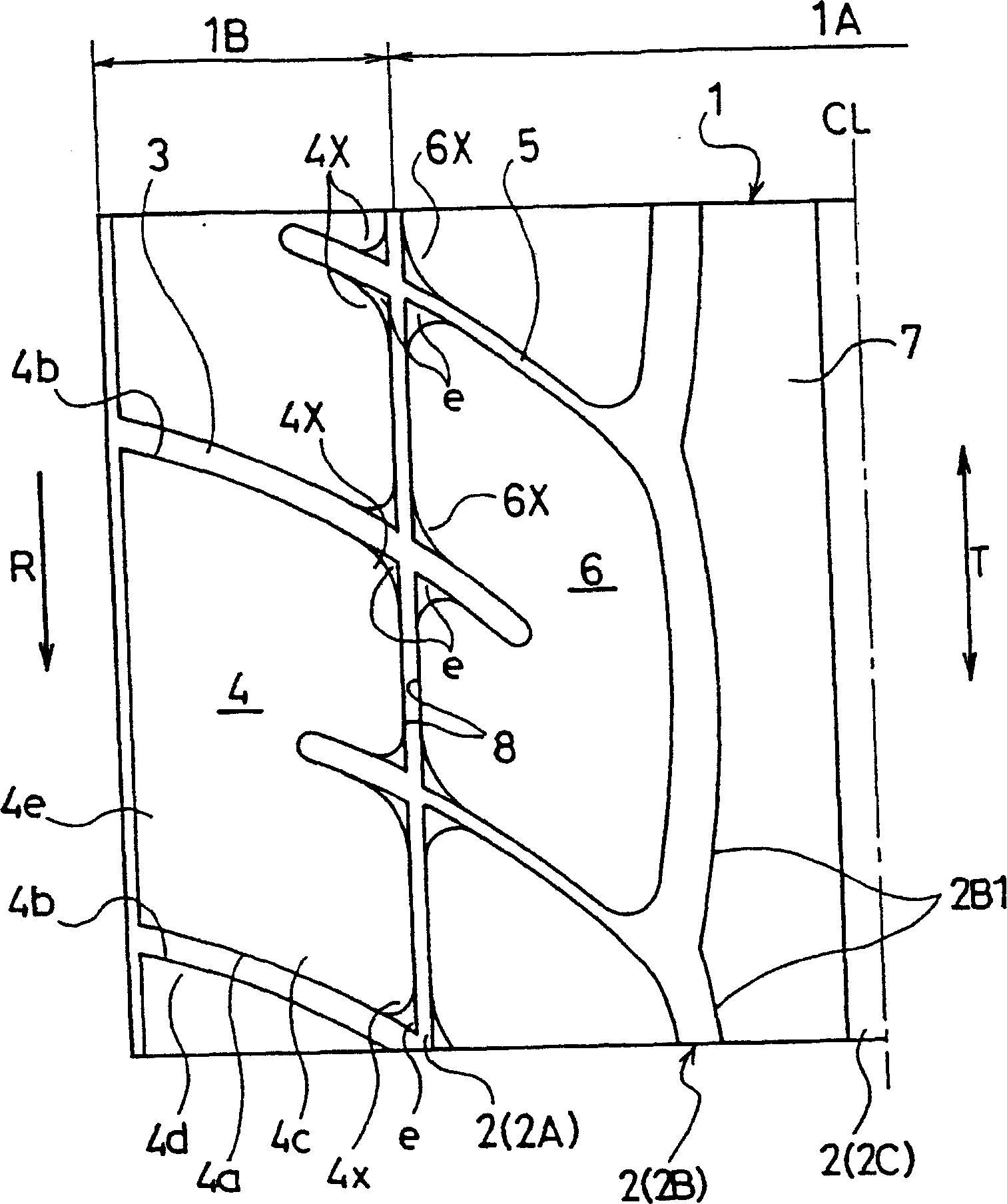
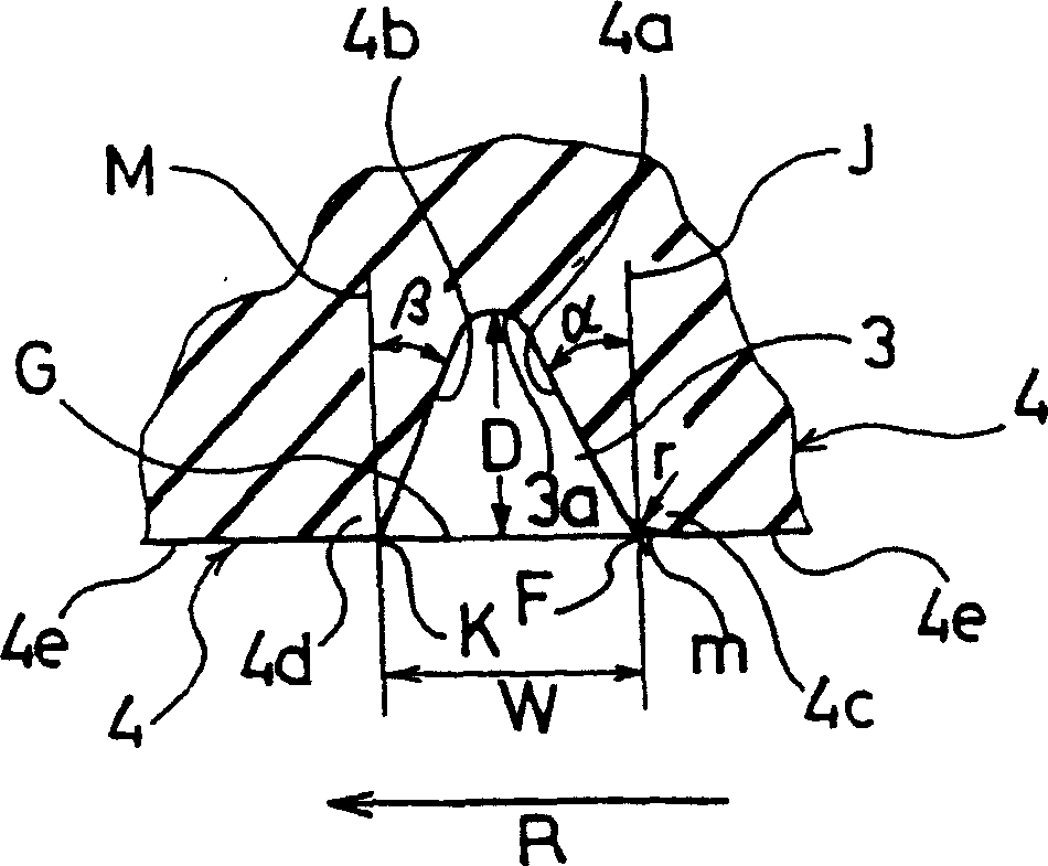
[0035] Set the tire size to be the same as 235 / 45ZR17, and set the tread pattern according to figure 1 Assuming the same, the relationship between the inclination angle α of the side groove wall surface in the tire rotation direction and the inclination angle β of the tire anti-rotation direction side groove wall surface of the block in the shoulder region is respectively made as β > α, and the tire rotation direction side edge The tires of the present invention were chamfered in an arc shape, the tires of the present invention were not chamfered at the side edges in the direction of rotation of the tire, and the conventional tires of the comparative tires were made with an inclination angle α greater than the inclination angle β.

[0036] In the tire of the present invention, the inclination angle α is 0.30×tan -1 (2D / W), the inclination angle β is 0.85×tan -1 (2D / W), the radius of curvature r of the chamfered surface is 3mm. The inclination angles α and β of conventional t...


PUM


Abstract

A tread surface the tire rotational direction of which is specified in one direction has a center region and shoulder regions on both sides of the center region. Blocks are defined in at least one of the shoulder regions by at least one first circumferential groove which extends in a circumferential direction of the tire, and first lateral grooves which extend in a widthwise direction of the tire and are disposed at predetermined intervals in the tire circumferential direction. Each block includes a tire rotational direction side groove wall surface having an inclination angle alpha , and a tire reverse rotation direction side groove wall surface having an inclination angle beta , and the inclination angle beta is greater than the inclination angle alpha . Each block has a tire rotational direction side edge portion which is chamfered.

Description

technical field [0001] The present invention relates to a pneumatic tire, and more specifically, to a pneumatic tire intended to improve uneven wear that occurs during circuit travel with a large lateral acceleration during cornering, or the like. Background technique [0002] Conventionally, various pneumatic tires have been proposed in which a tread is provided with a directional tread pattern specifying a rotation direction as one direction. Among the pneumatic tires provided with such a directional tread pattern, there is a pneumatic tire in which, in the shoulder area of ​​the tread, there are circumferential grooves extending in the tire circumferential direction, and a groove defined in the tire circumferential direction. The lateral grooves arranged at intervals and extending in the tire width direction are divided into blocks (for example, refer to JP-A-11-91313). [0003] However, in recent years, the loop track has also been opened to general users, and users oft...

Claims


Application Information

Patent Timeline
Patent Type & Authority Applications(China)
IPC IPC(8): B60C11/13B60C11/11B60C11/03B60C11/04
CPCB60C11/13B60C11/0302B60C11/1384B60C11/0316B60C11/04B60C11/11
Inventor 山根贤司
Owner YOKOHAMA RUBBER CO LTD
Why Eureka
Try Eureka